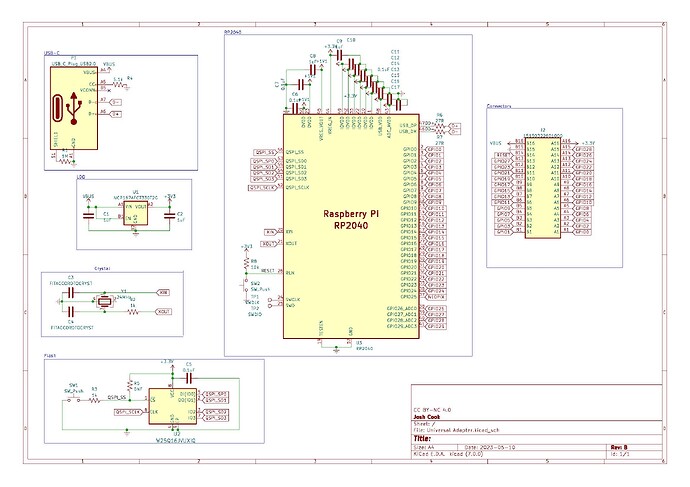
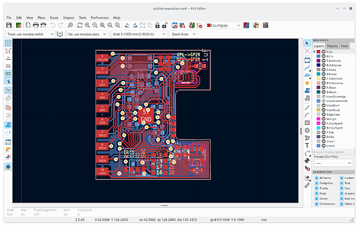
Any suggestions before I send this off for manufacturing? There will be a NeoPixel but I’m yet to decide sizing/package on GPIO25
Just for some additional context, this will have two parts, the expansion card and then the add-on boards, which is why there is that board-to-board connector.
oh wow I just finished designing my own. would have be really glad to see your post sooner.
Disclaimer: I am quite new to pcb design let alone working with rp2040. There are most certainly dumb things in the layout. Be kind to it
I made one in a single 2 layer pcb with 2.54 pitch headers integreated in module (tbh it is 2mm longer but lets not talk about that). Needless to say, compromises had to be made.
- no leds, figured I cannot see it anyway (but can be added by using solderpads)
- I have 20 pin out with 2 ground because I figured I won’t need more than that amount of IO
- 8 more GPIOs and SWD port are available on pcb as solder pads
- I have cheaped out on those filtering capacitors since it is just impossible to stuff them in there when I am using 0603 package for the ease of assembly. I boubt this will lead to any issue but testing definitely needed
Schematic
Layout
Update 2023-05-26
I just assembled one yesterday, it is not working but I think my solder job is the reason to blame. It was not showing up in dmesg (like you just need a pull up on d+/d- for a usb device to show up there) so I think the working condition of rp2040 isn’t met (lacking of power or crystal signal, probably). Will try to working on this over weekend but no promise made.
A photo of it
Also, current BOM cost is around $4.55 each and a realistic budget would be around $120 for 15 units. BOM is available here
Quick Update: nevermind just figured it out, used a wrong footprint for crystal. will fix & test that later
I’m at a very small 22mm x 26mm PCB, without the connectors it’s only 15x26mm, so a very small form factor, with 29 GPIO and a Neopixel and around 700mA on the 3.3V rail and ESD protection all exposed to a 32 pin header.
the amount of stuff you crammed in there is very impressive. However, I would not want to assemble this my self since I imagine it is 0402 sized component all over the place. Unless you put most smd component on one side then it can be done with a hot plate
Would you plan to sell assembled units? I would be really interested
Also, if you don’t mind, please release the layout and BOM.
Just chiming in, I’d be interested in purchasing a couple as well if anyone does a small batch production run.
Nice work! Impressive routing job. Can you explain to me the air wires around the USB-C cutout? Are those routing signals on the board, or between the board and USB-C connector?
I love these RP-2040 projects, for someone who does a lot of development, or on the move, for RP-2040 they’d be a lot more convenient than a Pico.
@Kris_Keillor They exist since I am using a usbc breakout board instead of a smd usbc plug which i admittedly should have
Finally got around to reviving this, but I’ve just finished validating my 1st unit.
These will come with 16MB of flash and all 30 GPIO are exposed + 5V and 3V3 along with the BOOTSEL and RESET buttons through a hole in the enclosure. The enclosure is open for the photo but will have a top snap-fit cover.
Neat! Shipping is kinda expensive to Germany, I guess I’ll ask around in the local hackspace if someone else wants anything.
@Josh_Cook I just tried to make an order and it’s not letting me place my order; it says
Unfortunately one or more items in your cart can’t be shipped to your location. Please choose a different delivery address.
I’m very confused, since I’m in NSW, and from your post you seem to be in Australia as well, so I don’t see any reason shipping shouldn’t be possible.
Do you know what’s going on?
I’m aware of this issue and working on a solution.
The issue has been fixed, I’ve also added a failover rate in case this happens at $11, but if you do see it, I’ll refund you the difference between what I paid and what you were charged.
Would be interested in getting one (I’m also from Germany)
This is sweet!
Do you have your pinout somewhere? Can i buy an extension cable somewhere so that i only need to plug that in in order to plug multible cables in?
@Josh_Cook just wanted to follow up on this thread to ask if you have any rough estimate when units may start shipping out? They look awesome!
Only just placed the production order due to extremely long lead times to get the connector used. ETA is 14 days to arrival.
Hey Josh! Just wanted to check in if there were any updates on the card? Looking forward to it!
Hey mate, any word here? I ordered one through your site months ago not realizing it wasn’t ready to ship and haven’t seen any updates here or email


