Ok, some updates.
Video of the keyboard fanning out: https://www.youtube.com/watch?v=7ovhgw8f3ok


Internal view. A stock Framework battery sits on the elevated foreground section. The black blob on top of the mainboard is a 3D printed representation of the integration board I mentioned in the last post. If you look closely you can also see a small green PCBA in the M.2 slot. This is a (pretty hacky) “u-turn” board I designed that breaks out all the M.2 pins to a FFC ribbon and relocates them to the integration board. I did test this using some breakout boards a while back and, while highly abusive of the USB and PCIE routing standards, does appear to work just fine.
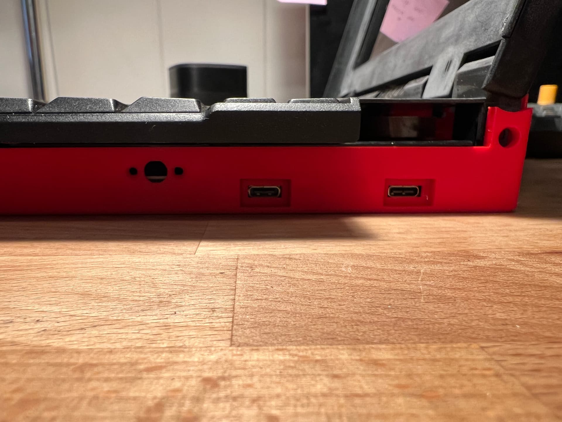
The two right-side USB-C ports are exposed directly off the mainboard. The three holes on the left of this image are for the power button. That internal assembly also doubles as the retainer for the M.2 “u-turn” board.

These are cutouts for a gigabit ethernet port and two USB-A ports that come off the custom hub I’m working on. I’ve put the USB hub board on the backburner while I get the laptop itself to a functional state, so they’re empty right now.

Back view showing the fan exhaust grille.
The integration board, along with a custom flex cable for the input cover connector, and a small board to hold the 701C indicator LEDs are all on order and should be arriving next week. Assuming I don’t hit any major roadblocks, I should have a largely working laptop in the next two weeks. At that point I’ll pivot to working on the USB hub and get the case shell printed on an MJF machine.
It’s also worth noting that most of the stock Thinkpad parts are either cracked, broken, or at least cosmetically challenged. These laptops are notorious for having brittle plastic and mine is no different. I’ll try to make it nice once I get it all put together and working, but for now I’m not too concerned about it.