@robodan918 Can we talk about X61 motherboard swaps somewhere? Do you have a plan for the power supply? So far this seems like a good lead. Laptop Battery Charger | Hackaday.io
1 Like
@luke_marvin yeah send me a ping on reddit. Robodan918
1 Like
Just awesome that you are working on this! I have a mothballed 701c in good condition that I would love to bring back to life. Original owner, bought it back in 1995 and loved every moment of using it.
5 Likes
A Wonderful Project! The last time I saw a similar project was the x61 update project of 51nb website. I also have two 701Cs in my hand, and I had the idea to update the hardware for it. But after such a long time, its plastic shell has aged and it is difficult to carry out such transformation, so I gave up. Very happy to see such a wonderful project.
2 Likes
For anyone interested, I wouldn’t recommend sacrificing a 701C to do this. They’re worth a fair bit (hundreds of dollars at current market prices) intact. I have a few disassembled keyboards I plan on modding to USB that could be used for this, and I have a source that might have a few spares.
4 Likes
This is amazing!
1 Like
@Karl_Buchka any progress on this to share? No pressure, just loving this and interested to see how it is going.
2 Likes
@2disbetter thanks for the bump! I had to put the project aside for a bit after the initial post, but as of about two weeks ago I’ve been back at it.
I finally got a 3D printer that can run the entire bottom case in a single print, so I’ve been working on refining the mechanical design. It’s about 95% there.
The other big progress is on the other PCBA that will live next to the USB hub. This other board is like the rug that ties the room together. It handles the keyboard, trackpoint, wifi/bt, lid closure sensor, indicator LEDs, power button, and some other housekeeping items.
I don’t have anything to show photos of just yet, but I should have a real update soon.
7 Likes
Ok, some updates.
Video of the keyboard fanning out: https://www.youtube.com/watch?v=7ovhgw8f3ok


Internal view. A stock Framework battery sits on the elevated foreground section. The black blob on top of the mainboard is a 3D printed representation of the integration board I mentioned in the last post. If you look closely you can also see a small green PCBA in the M.2 slot. This is a (pretty hacky) “u-turn” board I designed that breaks out all the M.2 pins to a FFC ribbon and relocates them to the integration board. I did test this using some breakout boards a while back and, while highly abusive of the USB and PCIE routing standards, does appear to work just fine.
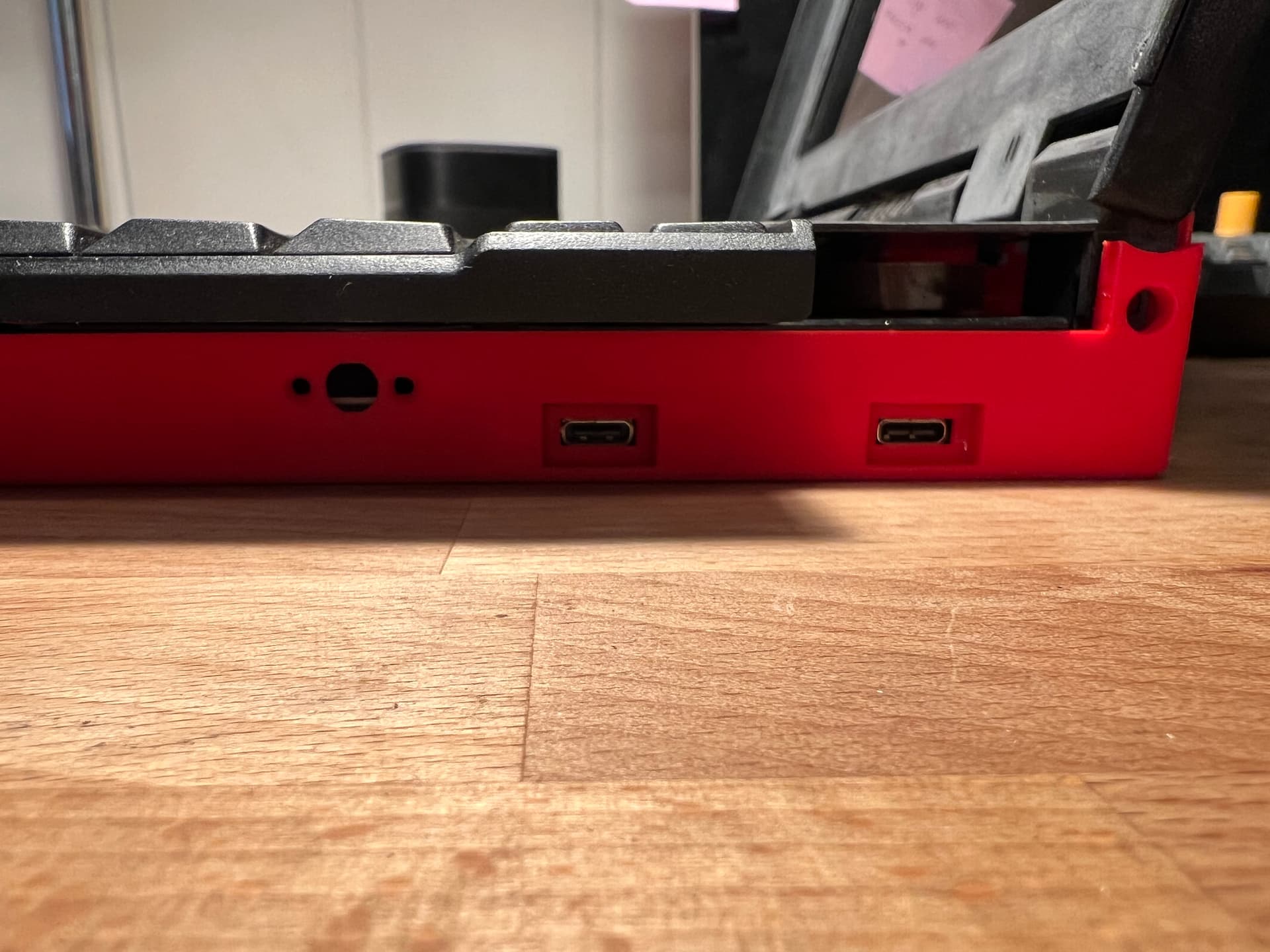
The two right-side USB-C ports are exposed directly off the mainboard. The three holes on the left of this image are for the power button. That internal assembly also doubles as the retainer for the M.2 “u-turn” board.

These are cutouts for a gigabit ethernet port and two USB-A ports that come off the custom hub I’m working on. I’ve put the USB hub board on the backburner while I get the laptop itself to a functional state, so they’re empty right now.

Back view showing the fan exhaust grille.
The integration board, along with a custom flex cable for the input cover connector, and a small board to hold the 701C indicator LEDs are all on order and should be arriving next week. Assuming I don’t hit any major roadblocks, I should have a largely working laptop in the next two weeks. At that point I’ll pivot to working on the USB hub and get the case shell printed on an MJF machine.
It’s also worth noting that most of the stock Thinkpad parts are either cracked, broken, or at least cosmetically challenged. These laptops are notorious for having brittle plastic and mine is no different. I’ll try to make it nice once I get it all put together and working, but for now I’m not too concerned about it.
15 Likes
Really nice thfrinkenpad!
2 Likes
Hi Karl, how did you solve the problem of the indicator LEDs? Is it controlled via the usb port?Thanks!
1 Like
Thanks, @Brunoais !
@Alvin, the indicator LEDs are driven by the same microcontroller that takes care of the mouse and keyboard.
@Karl_Buchka If I understand correctly, this microcontroller board should be connected to the mainboard through the usb-c port. The information of leds comes from windows api? in this case, are the leds of battery power and power not work when the device is turned off?
1 Like
The board is connected via USB, but since the same microcontroller that’s processing keystrokes is driving the LEDs, it does the keyboard indicators just fine.
The power LED and hard drive LEDs are easier since they only need to be on when the laptop is powered up.
The charging LED is the main issue. Unless I tap into the physical LED on the mainboard (which I don’t really want to do), it won’t work unless the laptop is powered on and I have a driver of some kind communicate that status to the micro. All in all I think it’s a small price to pay. I could also add a small light pipe to the side of the chassis so the factory LED is visible through the side of the case.
4 Likes

The integration board, top cover flex jumper, power switch board, and LED carriers came in today. Assembling them tomorrow and hopefully I’ll have a fully functioning Framework/Thinkpad hybrid.
15 Likes
@Karl_Buchka I hope you saw the shoutout from Nirav Patel during the live Q+A today! ![]()
2 Likes
@rednight39 I just saw it. Wow! That’s very flattering. Thank you, Nirav!
Here’s the latest progress shot on the board bring-up. So far I’ve just done basic power-on testing, but it’s looking promising. I haven’t let the smoke out of anything yet. You can see the flex cable connecting the integration board to the Framework mainboard. The small flex cable is for the power button.

13 Likes
I can only hope that my T25 mod will look half as nice as this one! Simply amazing.
1 Like
This is pretty cool! Thanks for the update.
2 Likes
Thanks, y’all!
I’ve got some more progress to report. I printed a new version of the bottom case with a routing channel for the eDP cable and a little cover to hold it in place. You can also see a small guide that lives in the screen assembly for the same purpose. I’ll likely wrap the cable in some chafe-protecting tape before I final assemble everything.

The keyboard and trackpoint are now fully functional as well. I’m using the power and USB lines that are present on the mainboard’s input cover connector. That’s the flex jumper you see on the bottom right. The keyboard row/col lines are connected directly to the Teensy 3.6 microcontroller. The trackpoint strain elements are run through a Sprintek 8707 trackpoint to PS/2 board, which then runs to the Teensy.

Video showing the keyboard/trackpoint in action: https://youtube.com/shorts/WDAGBpTVgM4?feature=share
In the video you can also see the new top cover I designed to replace the original part. Mine was in about 5 pieces and couldn’t really be salvaged. This new piece should also be compatible with completely unmodified 701Cs, so it might be useful to people restoring those machines.
The Caps Lock, Num Lock, and Scroll Lock indicators are working as well.
Main open work on the integration board:
- Test the lid sensor and audio board passthrough. (Missing a sufficiently long FFC cable at the moment)
- Test the wifi/bluetooth. (Have all the parts, just haven’t done it yet)
- Fix the power button PCB. (I goofed up the tactile button pinout)
- Fix some function key related bugs in the QMK firmware build. (Some Fn key combos put the key overlays in a wonky state)
16 Likes