Hey all, I am looking to use a custom LCD screen on the FW 13. This LCD screen uses a custom pinout that requires more backlight pins that is standard. I am looking to figure out how best to deal with this (most likely through a custom logic board).
I’m not familiar with this - specifically, would it be ok to take the 4 pins, put them together in a plane and then split them out to 6?
You could likely also just hook up 4 or the 6 pins, they are usually internally connected anyway. Assuming the 4 pins and the wires are capable of carrying the necessary current themselves of course, otherwise you are kind of screwed anyway.
Make sure the max voltage and IO-voltages match too when you are dealing with a non (de-factot)standard pinout.
I’m not sure if the naming convention (anode/cathode) makes a difference(ie, could it just be that it means positive / negative) / or indicates if it is indeed a screen with K&A connections? Elsewhere i found that it says the forward voltage of the backlight is 2.85V typical (min to max being 2.7V to 3.0).
So the confusion here is that what drives the power and/or dimming since the BL_PWM is not present and backlight voltage is constant.
Yep; you need a backlight driver for it, in short. That driver, then, will receive BL_PWM and BL_EN signals, and drive those LEDs. Also, that’s forward voltage for a single diode - your backlight might have multiple diodes in series? Gonna try and check the datasheet later.
Hmm, ok, this is slowly pushing the boundaries of my comfort zone. I however have on order the control board for the device, so I’m guessing someone has already manufactured this previously. Would be nice to understand the workings behind it though and build a custom board that works with framework.
Would it be ok to ping you to ask more - I have access to more info since i am already talking to the supplier but i just need to decipher the information
Just posting an update on my attempt at this and what I have reached so far with this: My use case is a little different - I have been trying to integrate the TL134GDX into my FW 13.
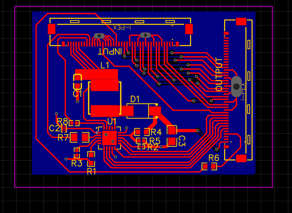
I have been running the screen with a USBC + DP driver board plus a breakout LED driver board(with the driver board purchased from the screen vendor):