Like PeetzOr said they are Thunderbolt 4 but are pending certification so they can’t legal advertise as T4. Unofficial and functionally they are.
The laptop has the 4 physical ports split into two logical PCIE devices. With the ports on the left side going to one controller and the ports on the right side going to the second controller.
All ports are PD3.0 and if I remember in another thread the team comment about running the main board without a screen or battery using a 100w charger (probably for cyberdecks) the battery can take a 1C charge rate.
So if i’m understand you correctly the port can only provide 15W ( 5V 3A Type C specification max regardless that it has a PD controller inside) and can’t provide eg 15V 3A if there is a PD device inside the expansion card to communicate out higher voltage? In other words there is a PD 3.0 controller in framework laptop , and if i put a PD controller into the expansion card i sill can’t get those to communicate so that the framework laptop increases the voltage on the VBUS pin?
how do you mean it can’t automatically supply 3A? For 5V 3A i don’t need a PD 3.0 controller on card side but only a Type-C Port controller configured in UFP mode only that will ask for 5V 3A.
i found the 3D file " ExpansionCard_threadedInsert.stp" but the expansion card doesn’t have the top of the housing. So we have bottom case 1.5mm then 1.6mm clearance-> then 0.8mm pcb → and then 2.9mm clearance to the top edge ( = 6.8mm) ( do i have to subtract the top case from 2.9mm top clearance?)
is the 6.8mm thickness measure form whole expansion card or is 6.8mm +1.5mm top case ?
Expansion card spec additional question:
1)
I need confirmation that i don’t need to use MUX on USB SS signals because the card can’t be turned around. Can you tell that the connected signals are the A (A1 to A12) signals on the USB C-type connector and B signal row is no use?
where is the pin A1 form the side of framework laptop on port C ?
2a) Is A row toward keyboard or toward bottom?
2b) IA A1 towards upper side of keyboard or toward touchpad?
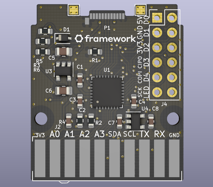
on the top of the MCU PCB is the A row because it has all the pins and the left pin beside the notch pin should be A12 as per molex datasheet
but if you look at the MCU image and MCU schematic then you see that from left the pin 5 is actual A5 and not A8 because it connects to R1 on schematic