I read a lot about how the USB-A cards cause additional power-draw even when no device is plugged in so I modified a card so it only uses power when a device is plugged into its USB-A port.
The Card signals to the main board that it is plugged in by having a 5.1k resistor pull-down to GND.
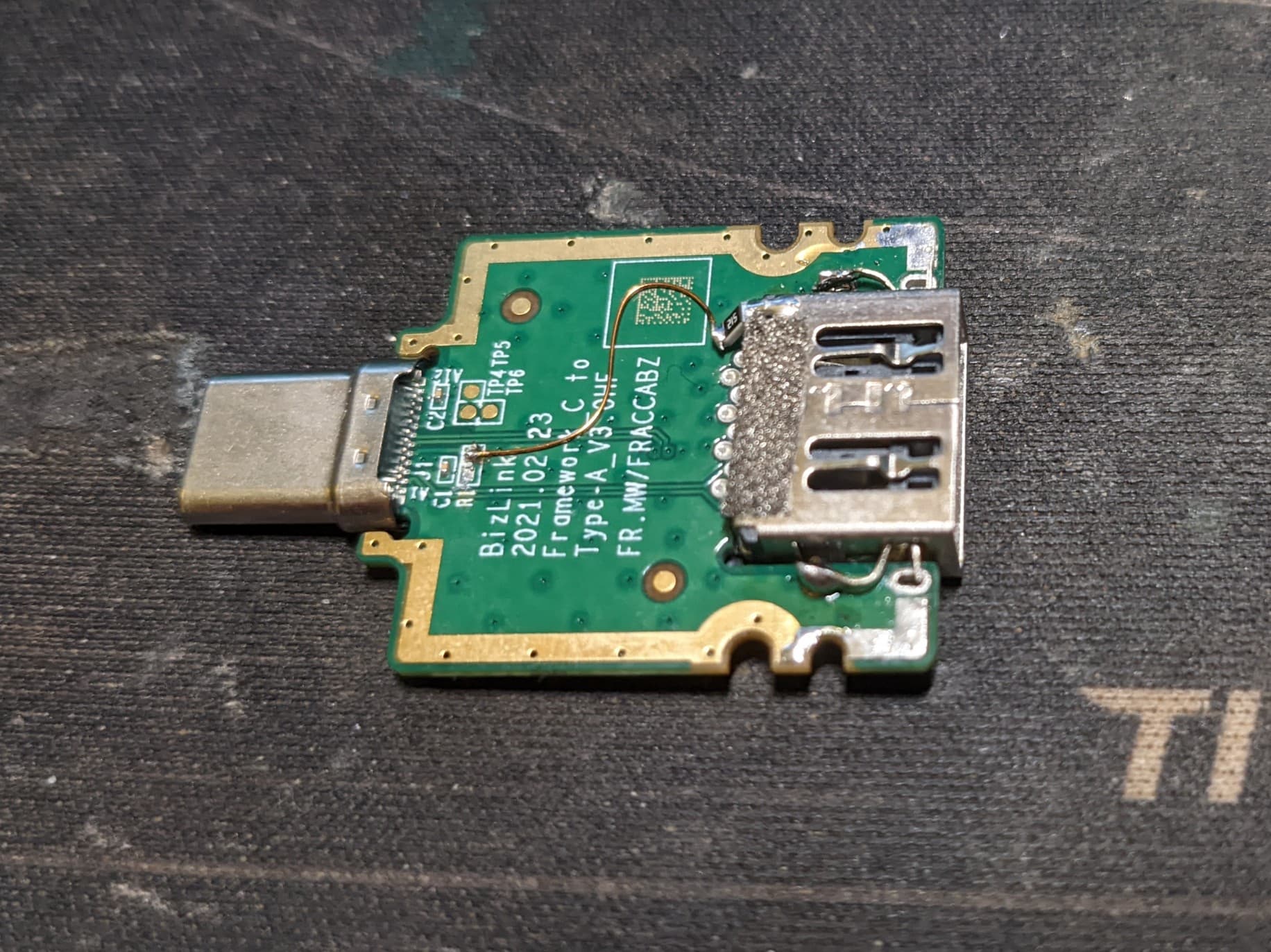
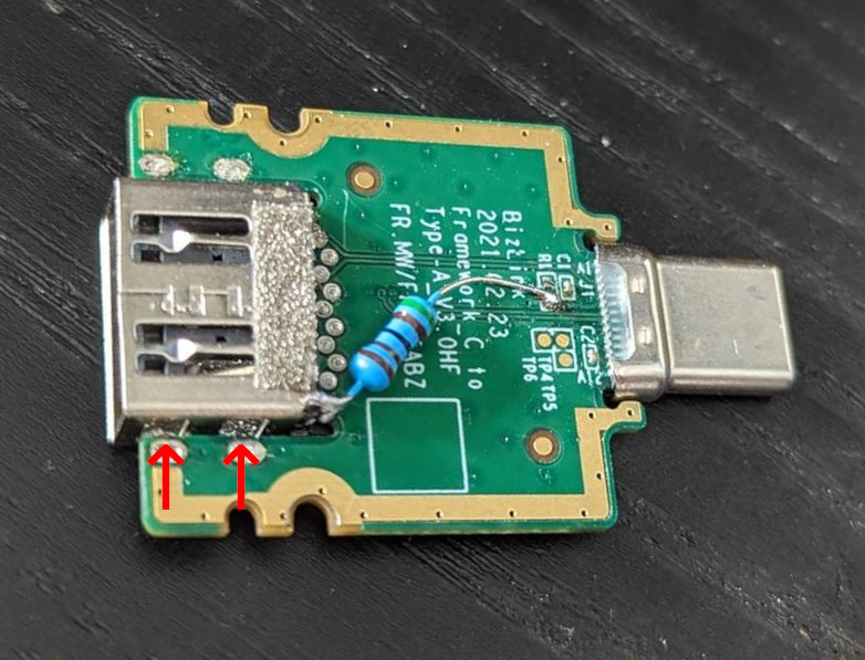
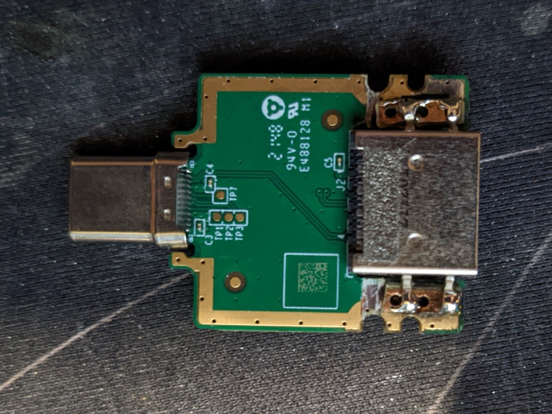
I started my mod by first isolating the shield of the USB-A socket by de-soldering the 4 tabs. This will isolate it from GND unless a shielded USB plug is inserted.
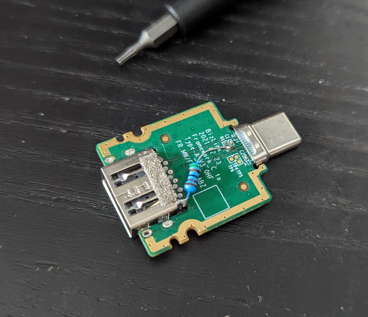
The next step is to remove the black 5.1K resistor. If you want you can just lift one side of it but it seemed to me like it was glued to the board before soldering so just lifting it will probably be hard. I replaced it with a large SMD resistor but the card has lots of spare space inside. You could even use a small through-hole resistor if you have nothing else.
I attached the resistor directly to one corner of the shield then ran a short piece of magnet wire to the CC pad the original resistor was soldered to. this concludes the electrical part. the next step is to mount the 4 tabs isolated from GND - I did that by cutting 2 pieces of perfboard and halving it so it became very thin. I glued these 2 pieces under the 4 tabs then soldered the tabs in place.
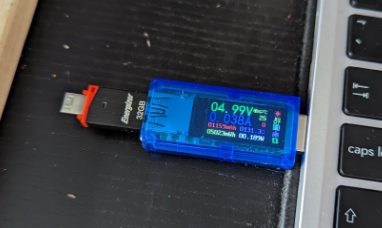
Done - your card can now be left in permanently without drawing extra power.
There is one downside to this mod: devices without shielding will not work anymore - that means a lot of stuff manufactured before the year 2000 or so but more relevantly it means that some shield-less yubikeys and drives will not work.
Also as you can see in the pictures I cut the top and bottom copper - you do not need to do that since it was an unsuccessful attempt to easily isolate the shield. The PCB actually has 3 Layers and the center Layer is GND so cutting it is impossible without completely cutting the board.
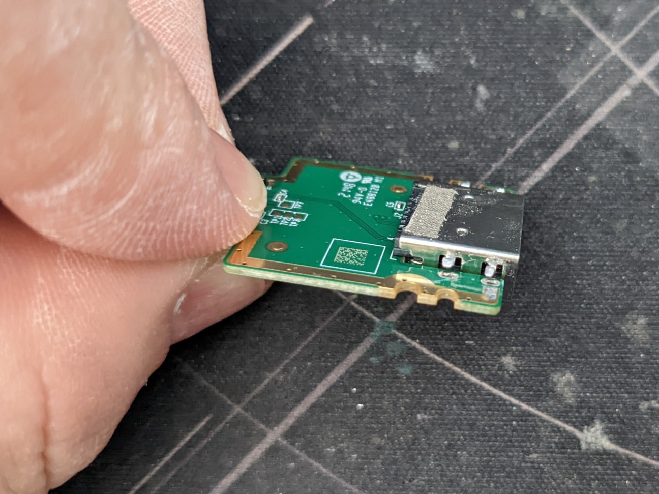
Here you can see how you have to pull and bend the tabs. In theory you can cut them but that might actually warp the plug more. Lifting them will break the shields connection to GND.
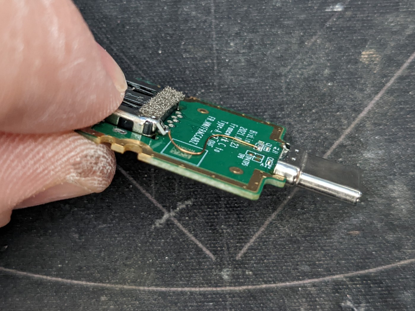
A side-view how to attach the 5.1k resistor - I angled it a bit but it is not touching the PCB or anything aside from the wire on its floating end. the wire is a bit longer in case the plug moves a bit in the future.
I used some longer pieces of perf-board this time to give the glue a lot of area to grip the PCB. I am reasonably sure this will stay attached for the useful lifetime of the card.
Yes - but I have nothing fitting at hand so my plan is to wait to see if its any issue - a simple short USB-A extension would do the same and I carry one anyway in my bag.
Also I recently surveyed all my USB cables and got rid of all power only and substandard ones so I couldn’t find anything i have that doesn’t work. I have to wait for the next cheap china thing to get here with a power only cable
Technically one can tweak the connectors plastic backplane and insert a push-button or a spring-lever there, akin to a card presence in a card readers that would connect the resistors.
That way it would work even for Yubikey-styled devices, since the button would be depressed by the plastic part anyway.
yes tho I feel that would be more difficult than to make a little routed PCB with some sprint contacts that match the holes on the shield. I have no idea how the pin contacts are routed inside the plastic. Also you need to drill that smh.
A hypothetical PCB only needs to be positioned then soldered
Okay, I have some more Data from the actual use of this hack - I found that many small dongles actually don’t connect GND and shield at all making them fail to work in the ports with my mod. I am testing a new version at the moment but it will probably need some kind of specialized board to make this practical long term.
I don’t have too much experience with USB connections, but shields are usually tied to a metal chassis. The shields are often not directly attached to the signal ground, it seems to be almost a philosophical question how to connect a shield .
For example this application note suggests an RC-filter between the shield and signal ground: AN 26.2 - Implementation Guidelines for SMSC’s USB 2.0 and USB 3.0 Hub Devices - SMSC (microchip.com)
I quickly measured a few USB devices I have laying around here, there’s everything between a “solid ground connection” and “not connected at all”, so the shield is for sure not a reliable reference point (and also not meant for that purpose).
I added 2 contacts made from a spare USB socket to the 2 sides of the socket. They are connected to GND. With this any metal enclosed USB plug will work in this socket. Sadly these contacts are a PITA to install and I don’t think most people would be able to add them.
AFAIK something (probably a DCDC converter) has to keep running to keep the 5v in the port going. Plus there are probably some switching mosfets and stuff. This draws some power and if the laptop is sleeping that will take days off the sleep time. This can probably fixed in firmware eventually (by just turning it ioff if there isn’t anything in the USB-A plug).
I ended up doing both of my USB-A cards in the end. Works well, I can get this laptop down to 2.19w on battop with tlp, powersave governor and lowest screen brightness
Haha I was about to answer - I had no trouble whatsoever but I hardly used the 1 plug I have in the laptop at the moment. I just checked it still works as intended
I see you didn’t add the contacts tho - you will need them in case you have a usb-plug with a not-connected shield. for instance the Logitech unifying receivers are like that.
I also hardly use those ports, but would be lost without them when it came down to needing one. The only devices I use in these ports are just a usb-serial, flash drive(s) and a mouse. Not much else. Most of them seem to be happy with this mod. I can always undo it but would rather have the battery life
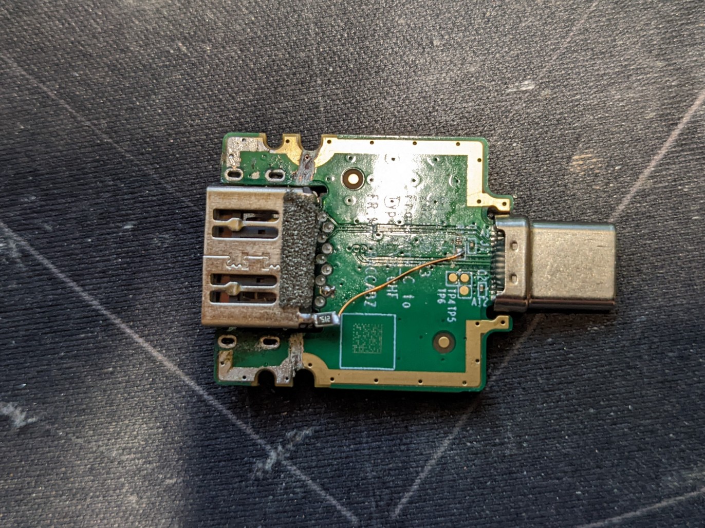
Would anyone have a caliper and be willing to measure the USB-A jack, particularly the location and size of the holes in the sides? And maybe post a picture of how far an inserted plug goes past the back hole.
(Tom_Haslett, hope you don’t mind me using your picture)
The holes look at least 3-4mm wide and couple mm high (starting from the surface of the pcb). Could be enough room for a switch. That way just inserting or removing a device or cable would activate / deactivate the port.
Unfortunately Framework just has a basic pcb file on their github which doesn’t include the USB-A port. I took a look though USB-A jacks on mouser but I didn’t see a matching one.
@Any Framework Staff who might wander by, could you perhaps give the part number of the USB-A jack?
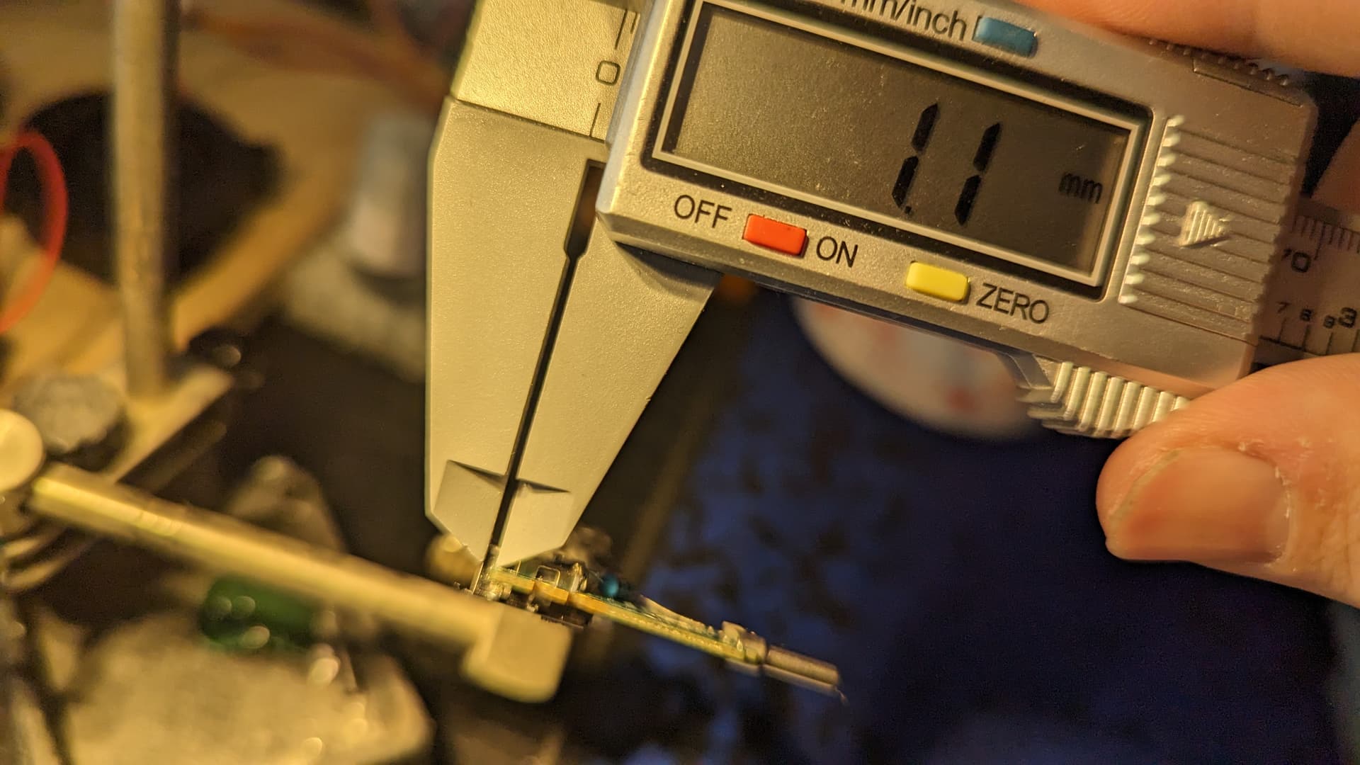
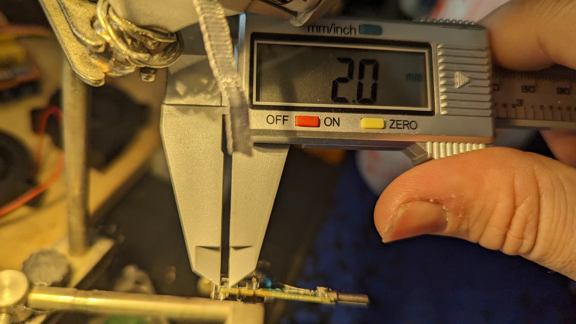
Height from the PCB seems to be about 1.1-1.2mm (couldn’t easily snap a picture of that).
Also, the 2mm measurement could actually be 1.8mm, I can’t quite see it properly (my eyesight…)
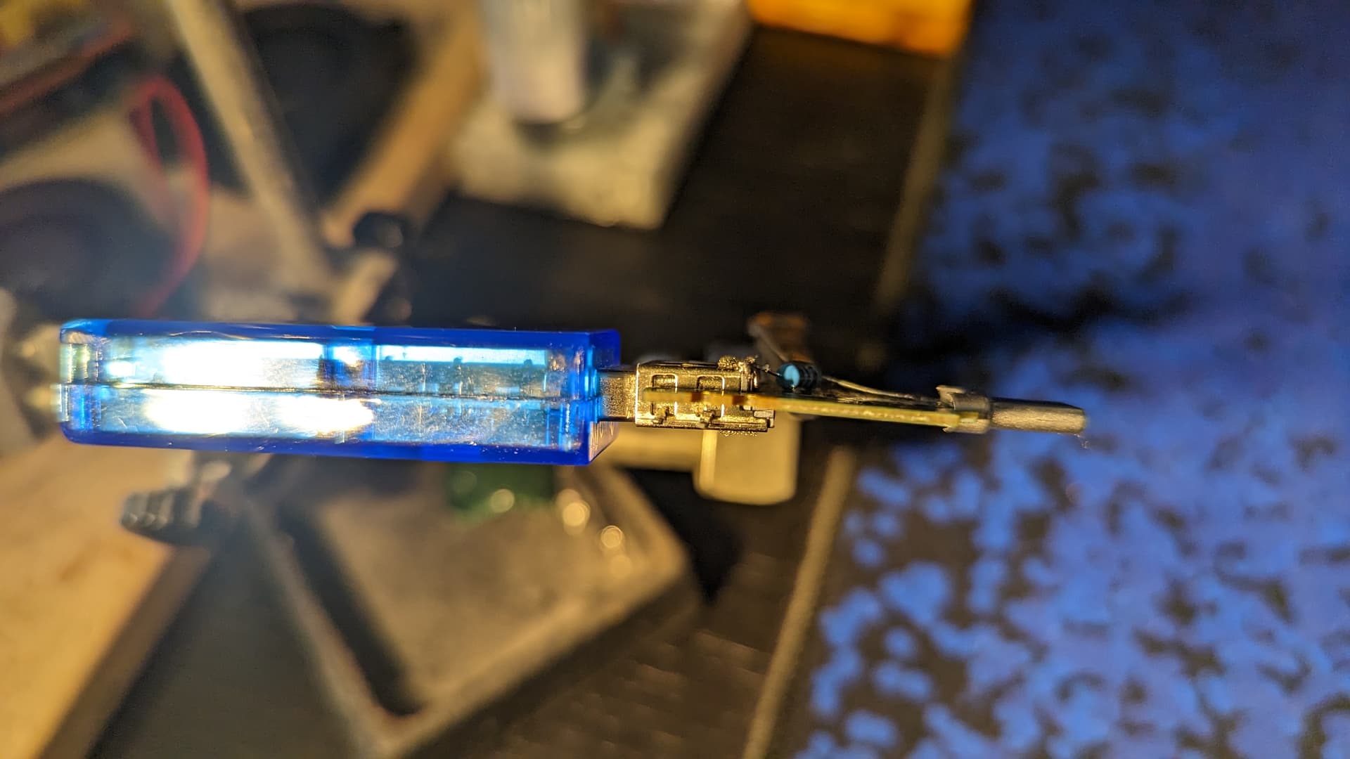
As for plugging in a USB device, it does cover both holes:
I suppose you could remove the piece between the holes to get some more room?
Also, the holes span both sides of the PCB, so perhaps remove a section of PCB is an option to allow for a larger switch? I can’t imagine there is anything important in the PCB layers in that corner?
PCB looks slightly bowed, may have been from the de-soldering of the tabs.


 .
.