Simple extra battery for the expansion bay

Ah ok, thanks for clarifying. I’m just a software engineer, so I’ll just leave the spicy computer juice for you guys to handle :slight_smile:

That really is a ton of capacity then, I’d slap it in my rig without a second thought. Granted, rectifying the controls and state of charge logic between two batteries is a bit tricky, but nothing that hasn’t been done (imperfectly) before.

1 Like

Just be really ghetto and make it like a power bank, then run a cable from the back to a usb-c on the side

3 Likes

Yeah that would be really ghetto. But I think would defeat the purpose of a Expansion Bay Battery. You would lose one USB-C port. You could just use a PD Powerbank instead but…

Tbh I’ve considered velcroing a battery to the bottom and doing this. For some reason it just doesn’t feel the same though.

i would not have it right in front of the exhaust ports. I would say it would be better to have the battery be most of the green space into the blue area behind it. the BMS can be a very small thing about the size of where it connects to the PCIe connector.

Those would probably be blocked off if this gets made. Although even if they weren’t it wouldn’t be a huge issue (would help keep the batteries cool) as the rear exhaust is purely for the GPU, and if the GPU is removed then the exhaust is just room temperature air.

1 Like

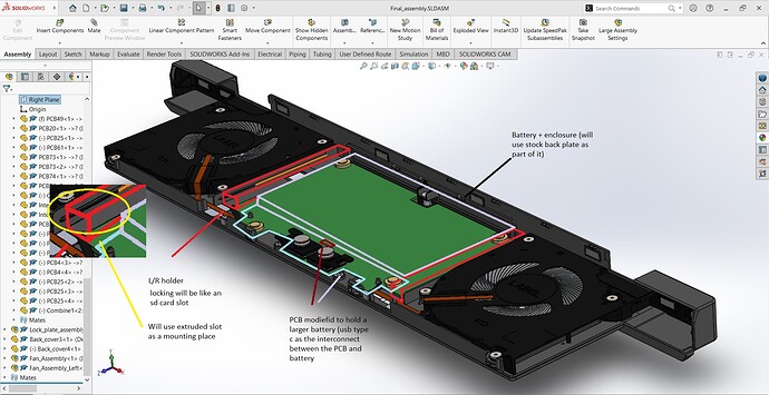
I went and looked at the step file for the expansion bay; it actually would be pretty easy to design an enclosure for the stock bay. For the past couple of days, I have been working on remodeling the enclosure in SolidWorks. Basically, re-assembling the parts with mates instead of everything being locked and uneditable. I am going to work on an adapter to house a battery. After that, it is a matter of having a custom board designed. I looked at the pin layout on the interposer, and it seems like there are dedicated pins for a battery module. I am no integrated circuit designer, so that will be the hard part. I have a photo of what I’m planning for it to look like.

9 Likes

We believe in you and bid you good luck on your quest :saluting_face:

2 Likes

Thanks man, after a bit of head-scratching It seems like I’ll be able to fit a 10-Wh battery with the stock slot (about 40min extra battery life per pack). But with a few adjustments to the slot, it is possible to fit a larger pack, which would be desirable. My intention with the pack is not to act as an extension to the laptop but as an external charging pack (in the sense that it will charge the internal battery rather than increase the perceived capacity). The pack will be hot-swappable, but I’m unsure if the majority want that. The capacity can be further increased if it isn’t a hot-swap pack. However, hot-swap would allow for multiple packs to be carried if need be.
I would love to hear some feedback on what people want in a battery add-on.

  • Hot-Swap?
  • yes
  • no
0 voters
  • Retro-fit back cover?
  • no, minimal modification
  • yes, more capacity
0 voters

That’s less than a single 18650, you sure you can’t fit more than that?

As in, the bay with interposer and fans will swap in and out or there will be a door or latch or something to slide only the battery in and out?

The stock slot (covered by a backplate by default) only gives me 5x57x110 mm of space to fit battery cells, charging, balancing, and USB protocol logic. To achieve 15v and 60W charging (I know this is less than preferred), I need at least 4 Lipo cells. That’s why it’s less than an 18650 cell (which runs at no more than 4 volts). I need the voltage, which decreases the capacity significantly. If things work out my way, though, I’ll be able to double or time and a half the capacity with a larger pack (by making a larger rear slot).

The battery will be separated from the rear bay. So it will swap out separately from it. Using a modified version of the rear slot that is covered by default. So you won’t ever need to remove the whole rear piece.

2 Likes

Just have it stick out a little in the back for extra power like how the GPU is. 10Wh is nothing really worthwhile to have.

1 Like

That is indeed not a lot of space, this thing looks a lot bigger than it is on pictures I suppose.

Apart from the volume lost to the cell hull, 4 cells with the total volume of one bigger one should not have signifficantly less capacity than one big one.

1 Like

It’s more the current levels, than Wh capacity. Lower voltage and higher Wattage (Power) gives higher Amp (Current). Which means you need to size up wiring, heat dissipation, etc.

60W@3.7v nominal (single cell LiPo) would be about 16.2a of current. 4 cell series is 14.8v, 60W gives about 4a of current. A LOOOOOT easier to handle.

Something like Protection Circuit Module (PCB) for 14.8V Li-Ion Battery Pack (10A limit) with Fuel Gauge Socket would be a fine BMS for this, able to handle up to 10a in/out continuous. I’d limit to 6 or 7 max just be safe of course.

And for max capacity, I’d use pouch cells, since they’re square-ish, so less void space.

If you’re physically removing it as well to “hot swap”, you need to also have some kind of protection container around it, so that cuts slightly into the volume as well. Plus you actually need an hot swap insert plug connector to hook up to the interposer to hot swap the battery in and out.

If you’re not hot swapping the battery in, that does simplify it. And yes, if the total size of the expansion card is enlarged a bit you can get a bit more space just fine, and not worry about protective case and insertable connector.

No, as @Blacksmith12 said, the challenge will be the interposer & logic circuit to handle the power out, and power in (charging from the laptop when plugged into the wall). In looking around for some other use case, I found BQ25713 data sheet, product information and support | TI.com which actually looks perfect for this, as it supports talking about the USB-PD stuff, talks I2C for a controlling MCU (probably some small Atmega or M0 or something, could be running Arduino perhaps?). Still not simple or easy.

2 Likes

That for sure, I mean there isn’t a big difference in capacity. This was in response to

Ah. It’s more that as you pull more current, actual usable capacity goes down after a certain point. Thus with a higher voltage (more cells), you can have lower discharge current, and get more usable Wh of power. See the Discharge Rate Characteristics charge in this battery cell specs sheet https://www.imrbatteries.com/content/molicel_m35a.pdf At 0.68a, capacity is ~3500+mAh, whereas at 10a it seems to be more like ~3300mAh, give or take. So by having more cells, even though each cell has lower capacity, you end up with more usable capacity. Also a lower discharge rate lowers the stresses and typically means longer life span.

This is a lot of super helpful info. You obviously know more than I do about stuff like this. Thanks for the help. I am currently just trying to get physical dimensions right now. The logic will come later; I plan to have an external contractor create the PCB and logic for the Laptop side of things and, if I need to, the battery side. Obviously, I would like to design it myself or get some sort of collaboration, but we will cross that road when we get there. In response to @Term_Grecos, that’s a great idea. I intend this expansion to be as sleek as possible since I’m figuring people who need the extra battery will be traveling to where slimmer is preferred, but I’m sure a little bump at the back can be justified for some extra capacity.

LOL, that’s oddly endearing. At least if you don’t have to put up with a friend stalking your forum use and trolling you regularly :wink:

Actually, I’m thinking that single chip might be all you need, almost. Doesn’t seem that it does balancing or per-cell low voltage/over charge detection. However, through a few short searches, found that BQ77915 data sheet, product information and support | TI.com can do the balancing and protection. Or perhaps BQ40Z50-R2 data sheet, product information and support | TI.com, which has SMBus, so can do battery gauge/etc.

I’ve actually been looking at the BQ25713 myself to do a custom board to combine a lot of things for a LED light up cane, and having to have the charging be external is a bit annoying, so I can’t just have a USB-C input and charge off of any USB-C source, even if slower with one lower than 50W source capacity (running 4s2p, figuring at 3a ~50W is the fastest I can go). That’ll be for another day though, to design the custom PCB and get it made. I’m NOT an electrical engineer, and I’m going to have to find some that’ll be willing to review the design to make sure I’m not totally screwing things up. At that amount of power the pack can contain, it’s potentially quite dangerous.

What’s also nice, is it’s right at about 99.2Wh nominal capacity, which fits under the 100Wh battery limit the FAA has, so I don’t need airline approval. =D

I do really want to design that charger though sigh

2 Likes