So found the Expansion Bay Specs thread, had a question on it, around this Expansion Bay Developer Program - #9 by Aaron_Baff
Ideally you would want a hot swappable system that gets screwed in as normal and then you can yank the batteries out and shove in a new one. But given how much battery capacity you get with the regular battery, anyone who is going to complain about size is going to have to accept compromises. Small battery packs are going to degrade far more than larger packs, especially if there is no way to set charging and discharging capacity. On that note please do not touch pouch cells if you are going that route. They are compact, yes, but they always fail badly and damage components when they do.
You will get far more people wanting a large battery pack over a small one.
Rather than that, have it stick out at the bottom like this:
That way it can have more volume while still being transportable.
Many reviewers complained about the FL16 being less mobile with the GPU module attached.
2 Likes
I thought about potentially having a bottom tray underneath the laptop, but I don’t know if intake fans will allow it. Also, that can make it less transportable, which would be why a hot swappable expansion bay would be best.
I believe the fans mostly come in from the back and vent out the sides (or reverse?), rather than anything underneath. I could be wrong about that. Obviously that’d add to the thickness, but could add a LOT of battery. However, something to worry about is total Wh, since there’s an FAA limit of <100Wh before needing airline approval. Probably would be fine if it’s just a large battery pack on the bottom of the laptop, they probably wouldn’t even notice it even if it’s >100Wh.
The fans pull air in through the bottom and top (the opening above the keyboard) and exhaust out the sides (and with a GPU module the back, but since this battery would be instead of a GPU module that’s not relevant).
Just leave the intake area out. You’d have to do that either way, even if not expanding to the bottom.
Just have the expansion bay act as a connector for the hot-swappable batteries.
That way the expansion bay itself doesn’t have to be hot swappable; only the battery packs have to be. And as they are hot-swappable, just take them out before transportation, if necessary, and reattach them again upon use.
Working on version 2? 1.5?, I haven’t really shown the version 1 publicly. Anyway, I have been taking a bunch of the considerations you all have made and improving the original design. The calculated capacity for this one is 17.76 Wh. I’ll post a larger update soon.
4 Likes
Battery Pack Version 2

Improvements:
- 17.76Wh battery
- 66.5mm x 132mm x 9.7mm
- LED battery indicator at the back
- Housing and case are two separate pieces for ease of assembly and repair
- less complex
- thumb grip for ease of pulling in and out of slot
Disadvantages:
- The back of the battery is not flush with the module
- capacity is still limited and not within the legal flying limit**
- shell is thin to accommodate the most capacity
- The rear stock cover needs to be modified along with other parts of the original frame to fit correctly (will most likely need to be replaced with a 3D printed chassis)
- tolerance issues with the frame rails
- The battery pack can only fit one way due to the Z asymmetry of the rails
- The cage is flimsy and warps out of the shell (I am guessing that the added PCB and cells will be enough to stiffen the frame)
**The FAA is unclear if two separate batteries carried by one device are considered one size.
Further development:
- I need the physical expansion bay module on hand to test Z clearance with the laptop. I also need to check if replacing the stock frame with a modified one is possible.
- Currently, the dimensions and circuits for the battery pack and the expansion module have yet to be specified. The most that has been discussed has been from @Aaron_Baff.
- The battery cells used to get the Wh estimate are from here (Model No. LP703051). I’m considering having a custom pack made to increase capacity further.
- I’ve been looking at the USB PD standard to see if the theoretical 14.8v the pack can supply will be adequate for the 45w spec.
- Looking at routes for development and ways of distributing products of this type. Thus far, the plan is to keep everything open source (it makes no sense to do anything else). 3D printing the cage, along with a list of parts for assembly and instruction, seems the way I’m going to go with it. Along with having assembly kits and/or complete units available. Currently, the battery shell and cage are hard to print; I’m going to work on optimizing the design for printing once a final design has been reached.
I would love to hear feedback (criticisms, improvements, thoughts, ideas, etc.)
Some more photos of version 2
note: the USB C plug is not designed yet but does fit within the current dimensions


17 Likes
For the FAA limit…just pull it out and carry it separately. Fixed. They’re fine with multiple <100Wh batteries that are carried/stored reasonably.
4 Likes
This is awesome!
I probably won’t be using this as I’ll be running the dGPU, but I love that you’re putting in the work for us :)
Regarding distribution: Wouldn’t it possible to use the framework marketplace for that, if the result is good?
I also plan to use the dGPU, so I won’t be using my own product. But I plan to create a hideaway second monitor that clips onto the screen. I could technically make a similar design for a clip-on battery module that mounts on the display frame, mainly for people who use the dGPU on the go and need the extra capacity. But that’s if it seems reasonable to develop.
I do plan to do this, but it’s too far down the road to promise that’s the case.
2 Likes
Hello Blacksmith,
it looks like you can get this working elactrically. If you can get it to work with 4 cells can you please test it with 4 18650 or 21700 cells externaly wired.
I dont know if it is possible with 5 cells, because that would be better for capacity and it needs lower current for the same power output.
For capacity you can see what is possible in my first post here:
2 Likes
The PCB/BMS is not nearly that large, generally. And I think it’s also been mentioned, but putting the 18650s there will interfere with the cooling substantially, which is a problem.
1 Like
The non-GPU expansion bay fans only exhausts out the sides, so 18650 along the back won’t interfere. Nrp even mentioned that location for cells in an early video about the FW16.
2 Likes
I thought I saw someone say it vented out the back, not the sides of the expansion bay. Hmph. Ok. Although we DEFINITELY want to make sure there’s a spacer, preferably some kind of slight insulation, between the vent and the battery. Lithium batteries don’t like heat like that.
1 Like
The GPU expansion bay has GPU heat sinks at the back and GPU heat exhausts out the back. The CPU heat sinks are at the sides, CPU heat only exhaust out the sides.
1 Like
I feel there is some confusion around the difference between the GPU expansion bay and the regular bay.
The regular bay that I have designed the battery pack for does not have room for 18650 cells at the back. But there is also no exhaust out the back, just the sides.
The GPU Expansion bay does have exhausting out the back and the sides.
The sketch @Chr made, is showing the GPU expansion bay. Framework, as far as I know, does not supply the CAD files for the GPU bay frame. I would have to re-design the stock frame to accommodate cells of that type. The only issue I see with this is how to effectively hot-swap the cells without making the bay and/or the battery pack clumsy to carry.
It shows the GPU shell, but since there would be no GPU, you either wouldn’t use the GPU fans, or you would create a plug to keep airflow directed out the sides only.
1 Like
Exactly. There is no GPU anymore to cool only the CPU.
And for Blacksmith:
The one with 21700 could be a little bigger and heavy. And i didnt have any hot-swap for the cells in mind. I would only design it in a way that you could easily swap out the round cells if you open the expansion bay (like the FW13 battery).
Also I just asked if you could test it with the cells
like in this (really nice selfmade) picture:
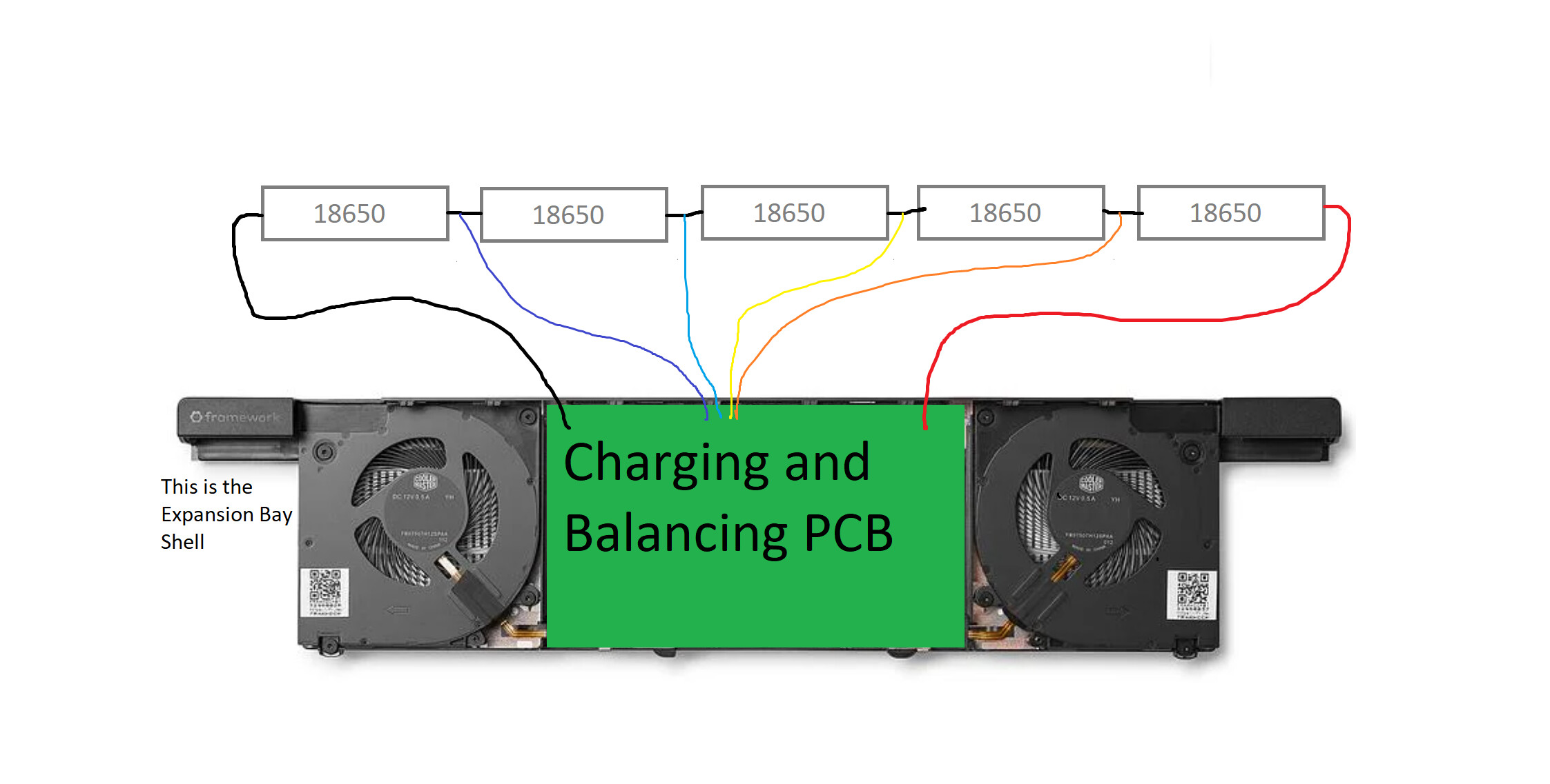
1 Like