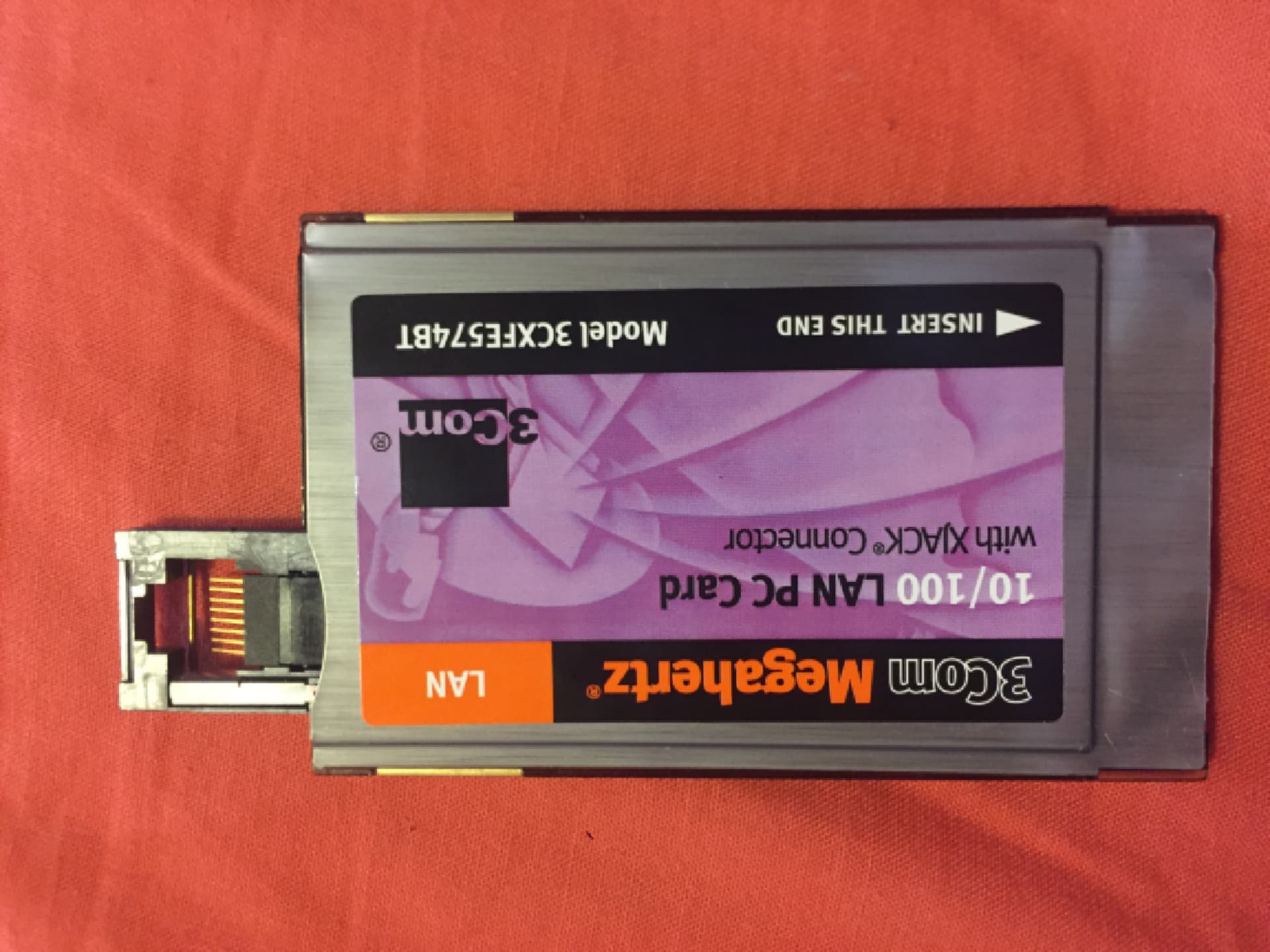
Can’t just be me who always wondered how these XJACKs worked, eh? got one on ebay for a tenner. glued shut of course
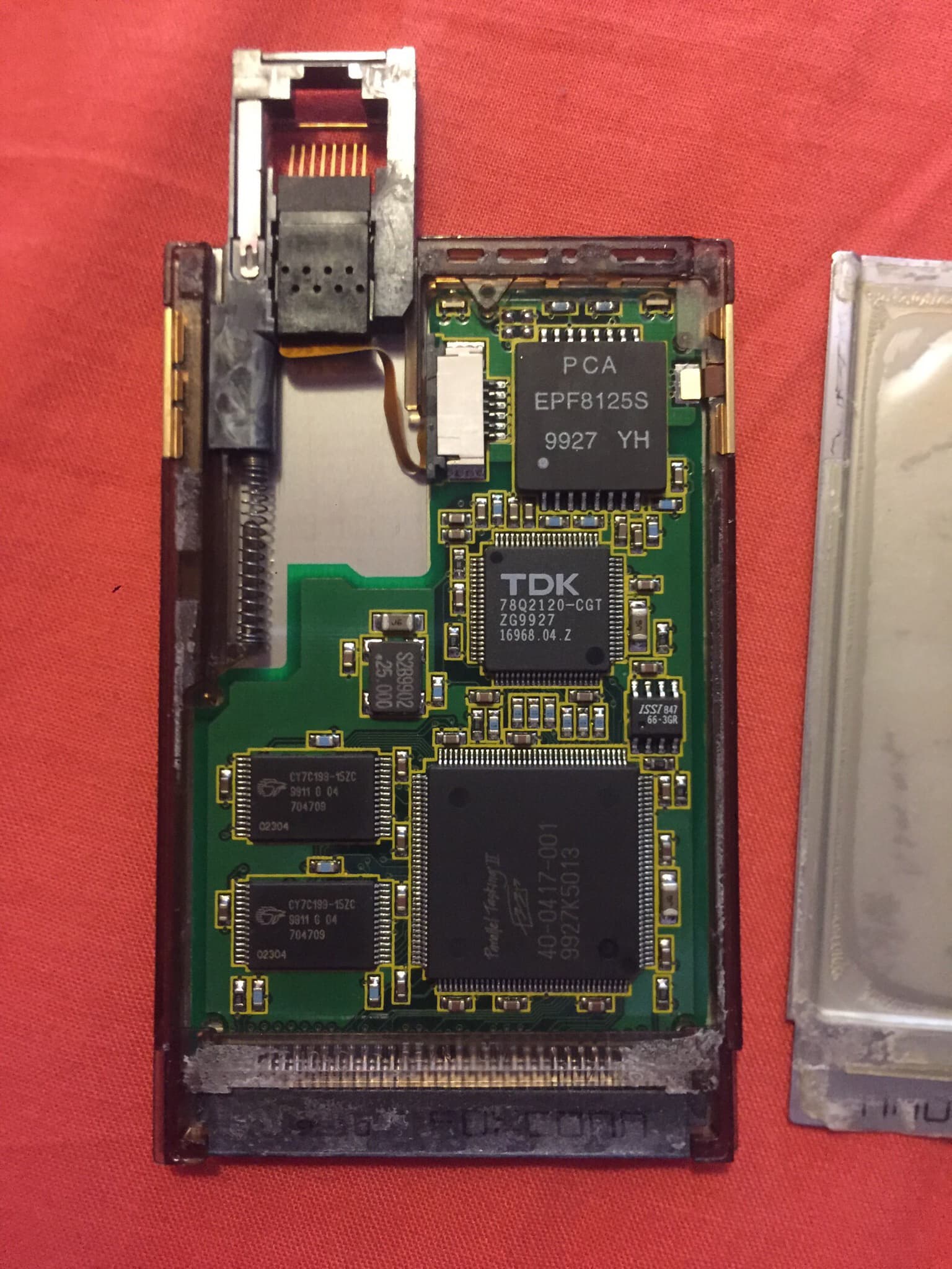
To my surprise, they actually have a flat flex cable between the ethernet port and the board. I figured this was how you’d do it nowadays, but I was not expecting flat flexes to be used in 1999! The actual mechanism of the popping out is pretty simple- it’s push push, like a pen.
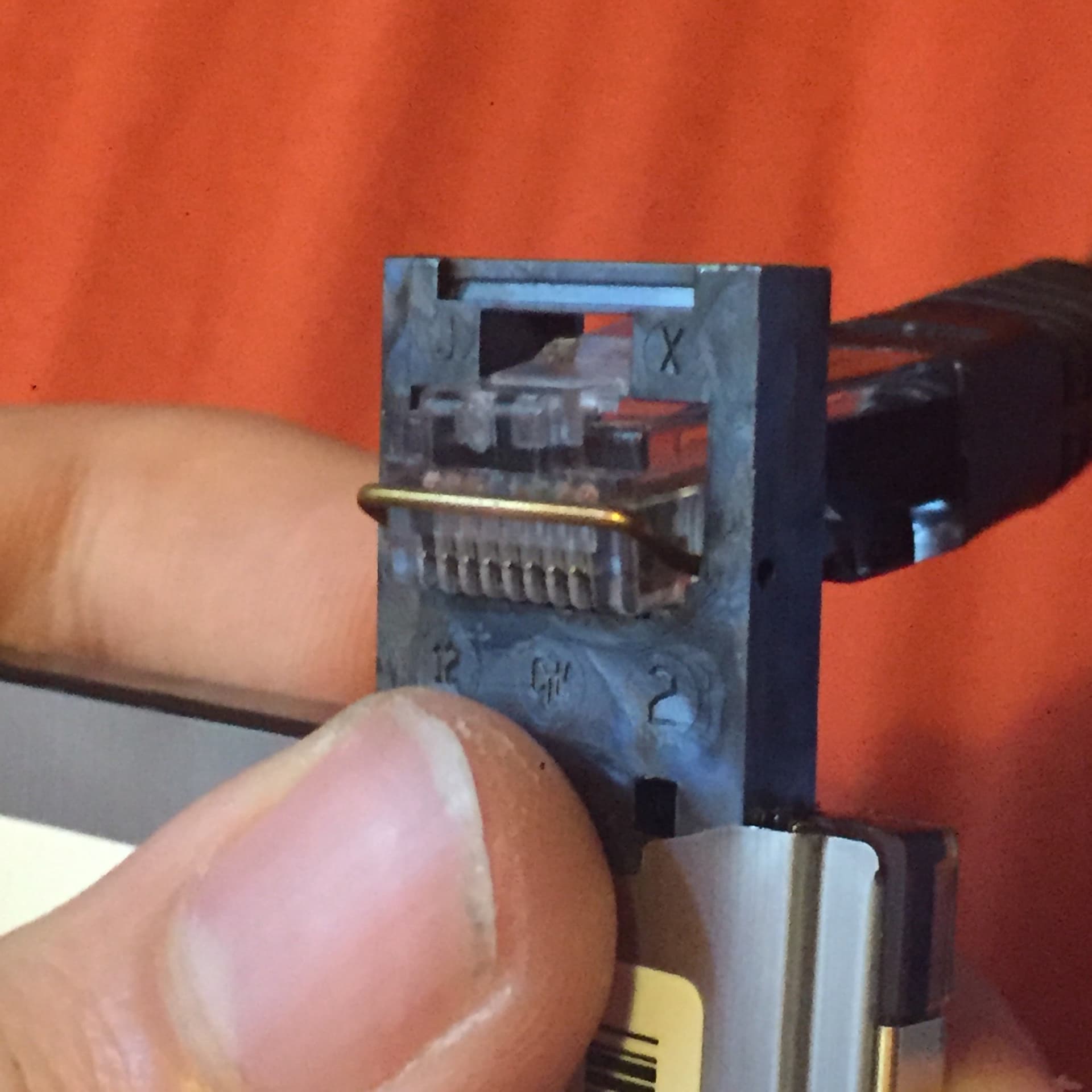
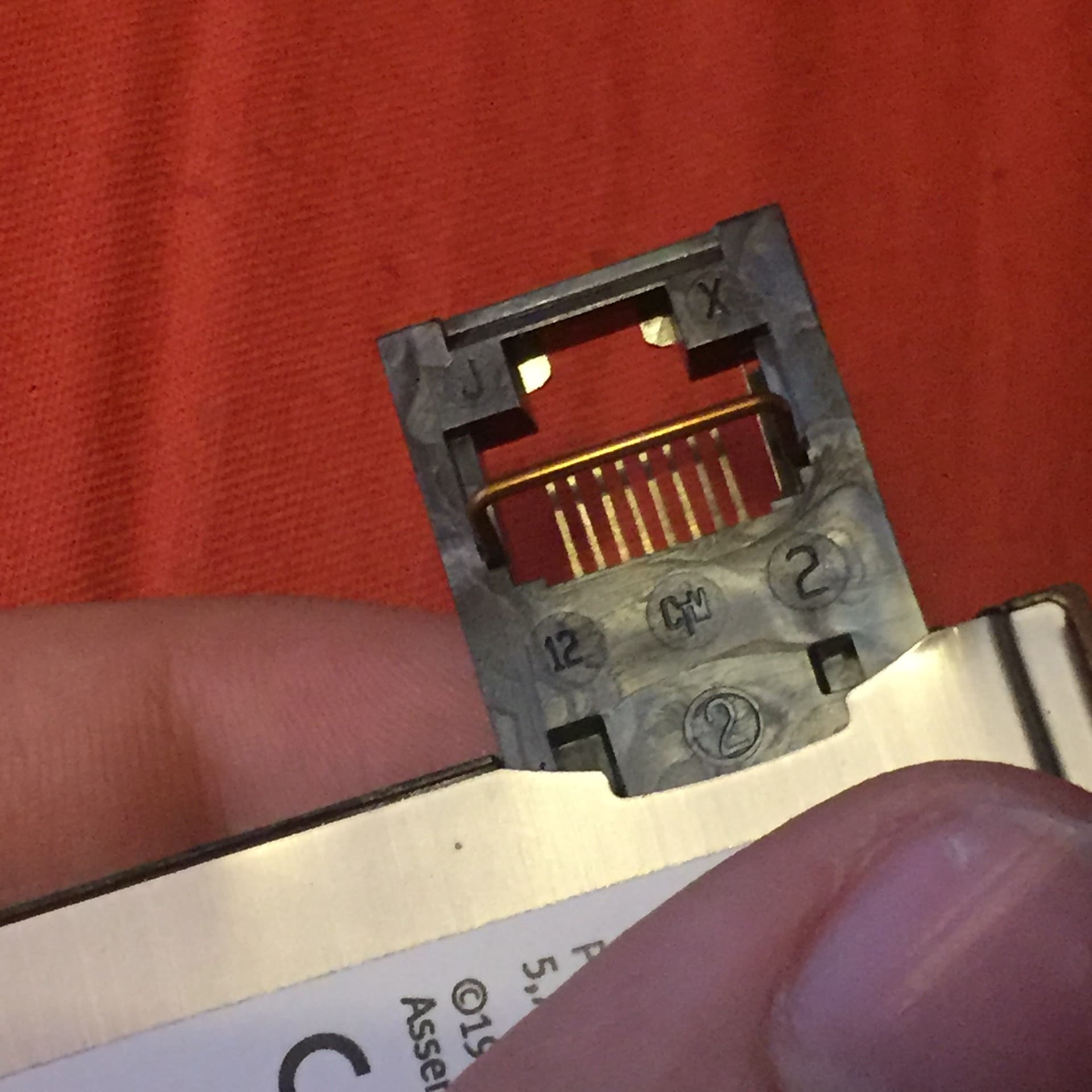
The actual ethernet jack is more interesting, though still rather simple. The plug is held in remarkably securely by the top tab. When you insert the cable, a small wire stops you from pushing too far, and the contacts spring back as they enter the contacts on the plug (they are very springy. if you don’t push the plug far enough to lock, they will push it out).
The whole card is 5mm thick, and the ethernet jack is 4.25mm thick and 17.6mm wide. However, it is quite long:
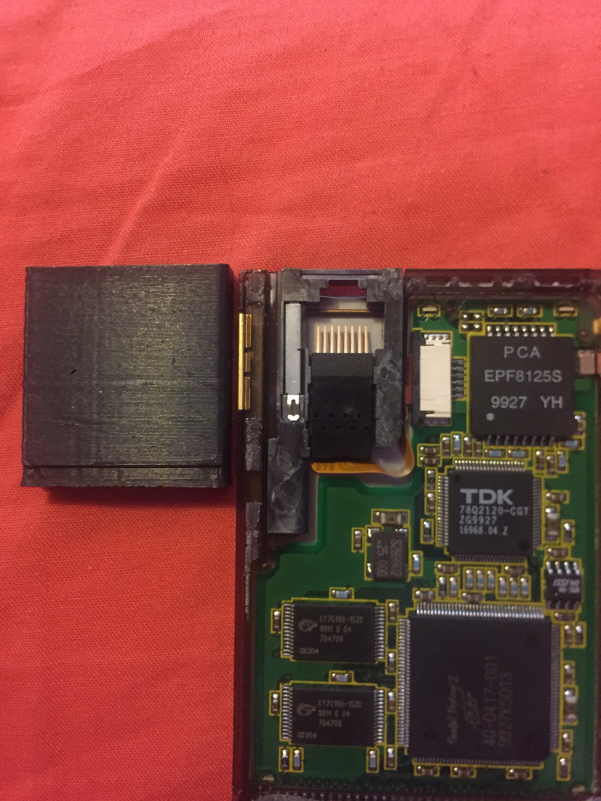
(black box is the size of an expansion card)
So thickness wise- yeah, it cooould fit in an expansion card. But keep in mind, there also has to be room in there for the electronics!

Janky quick check in fusion- if you have an “upside down” 0.8mm PCB, you can get a 4.25mm (there is probably room to make the whole thing thinner, but this is a known good baseline) space, and still have a 0.6mm thick bottom on the card. In this setup, you’ve got 1.15mm of space above the PCB- not a lot- you’d need to double side assemble stuff like transformers and the FFC connector onto the bottom, but enough room for passives and maybe even QFNs, like the ethernet controller (fortunately just one chip these days
So, yeah. MAYBE doable- if you can acquire those spring contacts, and house those in a (3D printed??) jack. Would be easier to stick to 10/100- gigabit requires a bigger controller, and twice the magnetics- not to mention the potential signal integrity issues of running gigabit through a flat flex, even a short one.