Im in the process of beginning developement on a module for the expansion bay that will have 3 slots for extension cards, to increase IO capabilities. Additionally to these 3 slots some other functionality would be possible to implement in this.
The idea is to design a pcb and some 3D-printable parts that can go into the ‘default’ empty expansion bay, replacing the small pcb that the expansion bay shell comes with.
Obviously this new PCB would need the interposer normally used for the graphics module, as the ‘empty’ expansion bay shell has a smaller interposer with only a few pins that are needed for the fans.
The expansion bay has 8 pcie lanes available via the ‘large’ interposer, which would allow for a lot more then ‘just’ 3 expansion card slots, so let me know what other suggestions you have to include in this. As I want to design the project to fit into the existing expansion bay shell, I can get at most one more small connector in next to 3 expansion card slots, but other internal things would be possible to do.
I have already looked into how I would design this and have found that unfortunately it is very hard for me (as a hobbyist) to get (very small quantities) of PCIe USB3 host controller ICs. (Im in germany, so buying stuff from digikey or mouser costs me 20+€ shipping and even those 2 barely have any such devices listed or in stock…) It is in fact so bad, that after many hours of research I found only a single chip that I could get from only a single european supplier and that does only USB 3.1 at best. It would almost be easier to buy used PCIe cards for desktop PCs and desolder the chips from those…
So, if I make such a PCB as described above, what would you like to see on it apart from 3 expansion card slots?
With the USB chip for the expansion card slots, I would still have 7 of the 8 PCIe lanes left to use for other stuff and a USB 2.0 line as well. Also as the USB chip I found has 4 USB interfaces, but there is only enough space for 3 expansion cards, there would also be a USB 3 connection left for something else.
Let me know what you would like to see me include and if you have any tips/suggestions for me!
Those three extra slots would be awesome, especially if they could accomodate the ethernet card without sticking out. Or a full-fledged USB 4 port including charging and video to connect a dock at the rear instead of one of the side ports.
I think the best use would be USB-C port that allows charging. The expansion bay interface is setup for charging, all FW laptops need at least one USB-C anyway, so that frees up the other 9 slots for anything else.
Second best option: An ethernet port, as the ethernet expansion card is to large and looks stupid.
I think video out is pretty much impossible without a graphics card.
Video In however would be easy, so the laptop could be an external display to something else
I’d like an internal USB-A connector for USB dongles.
I think that the expansion bay spec only allows for splitting the connection into two x4 connections, so unless you use a separate PCIe switch the USB chip will only leave 4 lanes left for one other thing.
Unfortunately the cutout at the back of the shell is only 7 mm tall, which is not large enough for an Ethernet port without either making a completely custom module exterior or making major physical modifications to the current shell. Neither of which are optimal.
Unfortunately to have a port support video it needs to have some connection to the GPU’s video output, however the expansion bay spec has no way to route the iGPU’s video output to the expansion bay. So video support would require the module to have a GPU internally.
Although it could potentially be a super cheap GPU that relies on the iGPU for most of the processing power. A DisplayLink chip (those are extremely simplified GPUs that have only the hardware necessary for controlling displays and rely on the other GPU in the system for most of the processing) could work (I’ve found DisplayLink products to work reasonably well, but plenty of people have complained about them, although I’ve only used their flagship chips).
As for charging, it is doable but would be limited to 90w to the rest of the laptop. Since the laptop wouldn’t have a dGPU that should be enough to charge it at full speed or use it under full load without draining the battery, however not enough to do both (I’ve seen my laptop reach 140w total with the battery charging at full speed while the CPU is under full load).
The RJ45 connector is only 6.5mm tall, plus the latch. So the only modification to the shell needed would be a small notch to accept the latch. That is, if the socket fits and can be positioned in the right hight to lign up with the cutout.
That sounds good. And as long as it’s not used for gaming, it should work okay. For gaming, you’d want the dGPU anyways or use one of the side ports.
That should be plenty. If the rear port is connected, the battery isn’t used anyway. And if absolutely necessary, it’s always possible to charge form the standard port like with video.
A USB C for charging/connecting to some kind of Dock was also one of my ideas and to some extend should be doable. The charging would be limited to 90W buts thats probably good enough for most scenarios.
I would love to make it USB 4, but I have not been able to find a suitable USB 4 host controller IC that I could get my hands on in low quantities and with a reasonable price. I spent probably about 6 to 8 hours yesterday searching the internet for these ICs and literally the only one thats at least USB 3 that I can actually get my hands on at a reasonable price is the UPD720201K8-701-BAC-A, which is a 4 port USB 3.0 host controller.
If you can find a USB 4 host controller IC that I can get from somewhere within europe at a reasonable price, do let me know!
Until someone finds a better option, I will continue designing with the UPD720201.
Video output capability is going to be really hard to do and I dont want to build an entire GPU into this thing, especially as that would require additional thermal design, etc, which is way more work then I have time for and am willing to do…
Video input should be possible, though it may need some sort of switching logic to tell the Framework when to switch to the video input from the expansion bay and when not.
RJ45 Ethernet, as described above, I suspect will not work due to the size limitation on the available cutout and I am not interested in designing a completely new shell for the expansion bay.
If someone else here is interested in designing and figuring out manufacturing for a custom expansion bay shell, I could always include the necessary parts for a ethernet connection on the PCB and just leave them unpopulated, but in that case that would be something I would do last.
I may have overlooked that. Either way at least one additional PCIe device apart from the USB IC would be possible.
Thats definitely an option, especially since most USB dongles are probably completely fine with a USB 2.0 port and there is a USB 2.0 connection on the interface to the mainboard already there and theres not much other use for that either.
Unfortunately I can’t be much help with that, however here in the US I see more options appear when I search for Intel Thunderbolt 4 controllers than when I search for USB4 controllers.
Since Thunderbolt 4 is just USB4 with a special certification (and getting the certification requires that certain optional USB4 features must actually be supported) I wouldn’t be surprised if Thunderbolt 4 controllers could work fine.
For that I think DisplayLink is the best bet, although I don’t know how difficult those chips are to buy.
DisplayLink chips are essentially GPUs (but they connect over USB 3.0 rather than PCIe) that have been stripped down to the minimum to handle display output and rely on the other GPU in the system for most GPU stuff.
I did the math and theoretically the expansion bay has just barely enough space for an SSD behind the expansion cards, however if the expansion bay had even 2 mm less interior length it wouldn’t be possible to fit.
Practically I wouldn’t be surprised if that would be the same scenario as the SD card expansion card is (ie. Theoretically just barely possible to make the stuff compact enough to fit, however takes a team of engineers a ton of time to make work).
Well, I wouldnt even try getting the PCB licensed, but I also couldnt find any Thunderbolt 4 ICs at any of the european distributers either, so I guess that wont happen anyways…
I had a quick look at some distributors and the 6.5mm might be the size of the RJ45 plug, but I cant find any RJ45 socket thats less then 11mm high and the socket is what would need to fit after all, so I dont think RJ45 is an option.
Kind of weird how every other type of connector has pretty much gotten smaller and smaller or been replaced by other smaller connectors over the years, but the good old RJ45 for Ethernet is still pretty much the only connector used for connecting something to a network (apart from fiber obv, but thats not consumer level yet)…
In the mean time I also had a look at some USB PD controllers and found quite a few options for those actually. For now I have decided to go for the CYPD4126-40LQXIT. For DP support I would additionally need a mux that can switch between USB data and DP data, but have not (yet) been able to find one. This is probably due to not knowing the magic search term that will find such a device though and I think when I find the correct search term I should be able to find something…
I will probably start work on the schematic on the weekend and try to put all of these things together.
So I had a look into these DisplayLink chips. It seems to be a proprietary design by Synaptics and only produced and sold by them. While they have some limited information on their website (basically just enough to know that the one to use for this project would be the DL-4120) and have some distributors listed, as far as I can tell you can only get these chips either from them directly or from a distributor (of which there is only one in europe) on direct inquiry. You just cant buy these ‘off the shelf’ and I cant even find a proper datasheet for them.
From that Id guess that they only want to sell to large customers and the datasheets are probably under NDA… All in all it looks like these are probably really hard to get in very low quantities and I dont plan on making hundreds of these PCB…
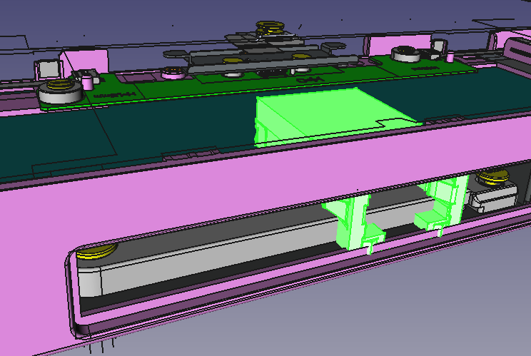
I did get the model of the shell and some slim line RJ45 connector together in FreeCAD, but without the actual part it’s hard to tell what is important, what can be removed and where the main body might interfere. Will have to wait for my laptop to get a real image of what is what. (Batch 8)