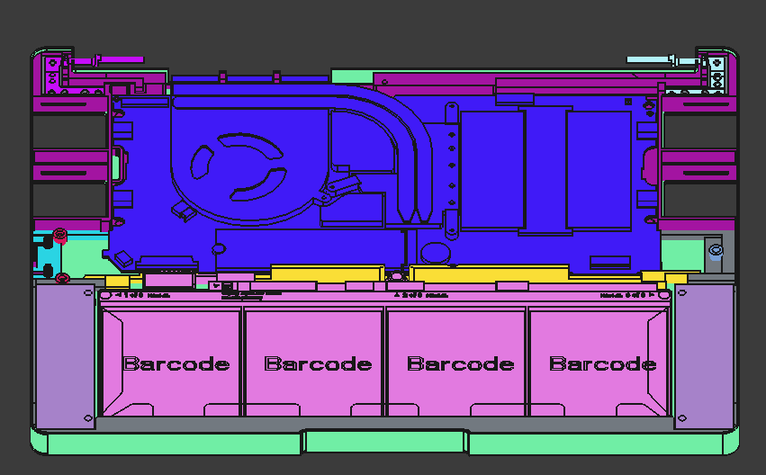
Following up from a post I made a few weeks back, here is my first attempt at a design for a 3D printed (or possibly CNC) lower chassis for the Framework 13. It was my first CAD project, so I’m sure it has many issues. One that stands out to me is the thickness of the side walls which in many sections is 0.8mm, although, maybe it would be okay with a fibre reinforced filament or something. Another thing: the hinge won’t open the full 180 degrees, although, a minor revision could make that possible.
I’ve borrowed extensively from the official motherboard case design (expansion card slots/motherboard tray/m.2 mount/etc.), and also a little bit from this Framework Tablet project (the middle bar in the frame, and battery/speaker screw dimensions), as I don’t have my own Laptop to base dimensions from.
I designed it to use these M2 heat inserts for all the screws aside from the hinges, which use these M2.5 inserts, and it should be compatible with the standard keyboard and display assemblies.
I hope this can at least serve as some inspiration to others to design some cool Framework things in FreeCAD! All things considered, I’m reasonably happy with the result, but any and all feedback is welcome as I do hope to iterate and improve this further. If someone could print it and show me what it actually looks like? That would be pretty cool too
Ahoj Zdeňku, this is great! I always wanted a thicker case that can accommodate a custom keyboard with trackpoint, but I never had time and skills to update the official 3D model. This looks really promising. Now I only need to find where to print it. Prusa MK3s is not big enough to handle it.
Ahoj! I definitely think a trackpoint could be possible very soon An X220/X230 keyboard should fit in a custom input deck design (sacrificing the trackpad), or maybe once other USB adaptors are available then it could be retained.
I’m really glad that you like my design, and I hope your print is successful. I’ve just updated the model to correct some structure and geometry issues, so make sure you try the latest versions! The only thing is, it might be a tight fit depending on the material properties of the filament and shrinkage, as I unfortunately haven’t had the opportunity to test it myself. If you have any issues, please let me know and I will revise the design accordingly when I am able.
Update: I’ve published the model to Printables under GPL3, and also to GitHub!
As for my next directions - I really want to experiment with custom input options such as a 3D printable input deck for a drawing tablet, or an Thinkpad X220 keyboard for example. I don’t have a FW13 yet.. but I’ll keep an eye out on eBay
Alternatively, I have an old Thinkpad x201 I’d be quite interested in fitting a FW13 motherboard into. I know some guys have had some success doing so with an X41, 701C, and even an old Macbook, so maybe with some time and dedication it may too be possible!
It does print on a sufficiently large printer – I was concerned about the bridges over the outside of the module bays, and the overhangs on the inside of the module bays, but they seem at least on visual inspection to have come out OK. The walls to the left and right of the battery area are too thin though – the bases of those snapped with some mildly careless handling within minutes of the print coming off the bed.
I haven’t tried to re-home my mobo+battery out of the printed slab it’s currently screwed onto, but maybe this weekend I’ll get the heatset bit out, put the heatset screw holes in, and do the transplant.
I’m still looking to refine the design further, as I definitely expected some issues. Unfortunately I don’t have a printer or a Framework (yet) to prototype myself :<
Please do share some photos once you assemble everything, it would be awesome to see it all put together. If you notice any extra clearances (particularly beside the speakers), I could reinforce the area there to hopefully prevent the splitting you experienced in future prints.
The printer is a ZeroG Mercury One.1 with a 0.6mm nozzle, the filament is Freemover PLA+. I’ll collect pictures after I have it assembled, but my setup is the motherboard + WiFi module + antenna + battery (no other laptop parts).
Ah, we will have to order M2 inserts; we used M3 on my current slab, and I assumed that would be what this used, even though you very clearly indicated M2 and M2.5
We could not get the battery to fit, but my other half is running the printer, and we’re going to slice out just those clips that are supposed to retain the battery on the bottom, and tune them to fit. If it’s a problem with the printer settings/print quality, we’ll fix that in the printer settings on our end; if it’s an actual problem with the model, we’ll let you know. For what it’s worth, the general “width” of the tips of those ears on the bottom of the battery seem to be <1.33mm by the calipers, but they are flared/flanged/filleted such that it could be interfering in other ways than just “the slots are too thin.”
Maybe it will be better to just remove the bits from the notches in the design down there… I don’t think the battery will move around too much without them in place. I’ll have some time tomorrow evening to revise the design - so any quirks you run into I can smooth out then, or instead later in the week.
The M2.5 inserts are only for the hinge mounts, so you can skip those if not installing the display assembly. I went with M2 as it allowed for the battery to be screwed into a metal insert, rather than just plastic as was the case in the tablet design I referenced.
Bottom case side walls there openings are way to thin. I wish i could design with cad myself. I am just collecting all the files myself i could find and then i have full .stl files i will try to 3d print it in clear resin or something like that like full laptop case. To bad there many variations of laptop. I bet bottom case for 13 wont fit top to 16 laptop.
Thanks for making this! Just printed on a Bambu H2C with translucent PETG, and I’m shocked at how great it turned out (no offense intended, it’s just a very complicated model).
Actually was able to mostly get the input cover on, with both bottom screws connecting perfectly. The back near the power button/hinge is where things get a little wonky. Can’t fit in the fingerprint module, and the center rear screw hole would require a comically long screw (plus I just think there’s too much material to fit right).
Overall a FANTASTIC start–I love this community, and if I get some time before my wedding might try to remix your model to help out (although I’m not optimistic I’ll have time).
This looks awesome, I love the colour so much! I spent two weeks on this, but I don’t have a printer (yet…), so it’s pretty cool to see it exist for real as well. Hopefully it doesn’t take too much work to get it polished into a more usable form, as I can’t wait to see it all put together some day.
Thank you, and yes! I hope many people build many things with this as a starting point
Edit: After seeing the new 13 pro (very cool) - it might be simple to modify this to accept the larger battery etc. so that people without easy access to the replacement bottom covers might be able to produce one themselves (maybe even out of 3D metal)? The new speaker design might also allow for greater reinforcement at the sides, but I’ll have to wait until I can see from all angles in a 3D model!
Hello, I am kinda confused with this. Will i be able to use the battery and screen and stuff like the camera and keyboard with this? One of my friends is giving me their old framework mainboard and i want to print the chassis and just buy stuff like the screen. Will this let me do that? And is it possible, if later on I wanted to get the 13 pro mainboard, will i be able to put that in it also?
Yes! (at least I think so…). I haven’t personally tested the design as I don’t have a Framework, or a printer (ram market has crushed my hopes and dreams), but the print by @kdarland looked amazing, they said they were:
able to mostly get the input cover on, with both bottom screws connecting perfectly. The back near the power button/hinge is where things get a little wonky. Can’t fit in the fingerprint module, and the center rear screw hole would require a comically long screw (plus I just think there’s too much material to fit right).
So it might need some slight tweaks to fit perfectly, but its definitely doable, and should be compatible with the Framework 13 motherboard (I think the pro one is compatible), battery, (original) speakers and battery.
If you do want to go through with this, and are willing to work with me, I’d be happy to iterate on the design if you run into any issues and can provide measurements etc.