This likely is a dumb question but is it possible to cut away some fo the back covering of the display panel and use light from there to illuminate things, similar to how I presume that it was donr in older apple laptops? Then you might be able to cut out the entire metal logo and put in a plastic one, potentially gluing the metal center of the cog back into the plastic insert.
1 Like
That was actually my original plan, there’s just so much more risk involved.
I don’t know how far to cut, or what exactly the insides of the LCD are like, so the odds of me ruining an $180 screen aren’t low, and that’s not a risk I really wanted to take.
It would be a better way to do it, and it is how the older MacBooks did it, but I don’t quite trust myself to make those cuts.
2 Likes
Maybe you could put out a request for broken screens, if someone has one with a working backlight but broken LCD, for example, they might be willing to try cutting into it or ship it to you. This community can surprise, you never know. Or possibly Framework themselves would be willing to send a broken one to you. Best of luck, I’ll be following this to see how it all works out for you! Very cool project.
1 Like
If nothing else, a broken LCD’s diffuser sheet could come in handy. Cutting out the right shape would require a good stencil or jig and a steady hand, or a laser cutter though.
2 Likes
Just curious - what is the diameter of one of the original holes?
The original holes were actually two different sizes, two of them were larger than the other four, which you can see in the images above. The smaller holes were ~2mm, and the larger ones ~2.4mm.
Have you considered using surface mount LEDs? The lens on these should poke through existing holed, and wiring them up shouldn’t be too fiddly (note that pads are on top, tho - but they probably wrap around to allow bottom soldering, too), and they’re 3.3v, too. You might be able to get away with just three of these - they’re bright - and use three mounting pegs:
https://www.digikey.com/en/products/detail/inolux/IN-S124BRUW/7604956
The smallest lens size might be mountable in/on pegs if your 3D printer is detailed enough (also pads on bottom, possibly wrap-around pads, 3.3v) :
https://www.digikey.com/en/products/detail/inolux/IN-S124ARUW/7604949
Something to consider. Also, PCBs are available that are super-thin (.2 and .4mm), and might be better than a flexy circuit.
Doesn’t look like there is space available for those LEDs. Those are 1204 package size, 3.2mm L x 1.2mm W. And the lens heights are more. There is so little space available that he probably wants to go with a tiny 0402 package, 1mm L x 0.5mm W. Some have really miniscule heights. Like 0.25mm EAST10052WA0 Everlight
Polyimide flexible PCBs are available in 0.11mm. PCB Prototype & PCB Fabrication Manufacturer - JLCPCB
I didn’t update the thread, but I actually ordered PCB’s a couple days ago, they should come in next week.
I decided on using 18 of these 0402 LED’s, which are miniscule, and should be very low-power.
I wasn’t after brightness, but rather a uniform glow, so I put 18 of these, two for each large hole I had created and one for each small hole.
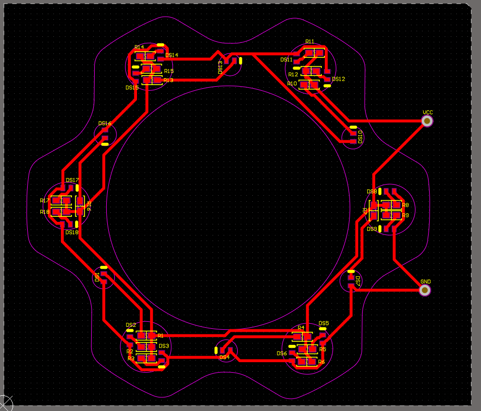
This was the PCB I ordered. I managed to get all of the diodes and 0402 resistors for them into the holes I had cut in my lid (the pink outline was just so I could line everything up).
The thinner PCBs were considerably more expensive, so this board will just be 1mm, and if I need thinner I can order it later.
The VCC and GND ports are through-hole, so I should be able to put the top of this board right up against the inside of the top cover, and then solder to the back. I may have to file the holes a little bit to get everything to perfectly align, and I’ll be really careful about shorting, but I think this will work super well.
The resistors I had installed on the board are 1k Ohm, but I think I have the leeway that if I needed to make them even dimmer I could add a resistor in the wiring to wherever I pull power from.
The goal is still to pull power from the fingerprint sensor LED, as it does the cool pulsing thing when the laptop is asleep, but I could easily pull from the webcam/mic module as well.
3 Likes
The idea is that the lens assemblies would poke through the holes, into the 3D printed logo - the rest of the component would stay “inside” the screen housing.
0402 components are tough to place by hand, if needed, and typically pretty dim - although the ones you linked to are very bright for the size. They can’t be driven straight from 3.3, so some resistors will be required (not a big deal, but extra cost/effort, potentially).
Flexi is fine, but harder to design for, and (far) more expensive… worth considering a very thin PCB instead IMO. You can reflow a .2mm/.4mm PCB in a toaster oven. Flexi is much less DIY friendly.
I used to have a surface-mount electronics factory ![]()
I’m super curious to hear how this design works out. Some questions:
Have you tested the boards yet? Hard to tell, but it looks like there are some missing traces - around R11? Not sure if this is a two-sided design, if there are vias, so could be wrong about that.
How much vertical space/clearance is there on the inner part of the lid? Is PCB warp an issue?
Are you doing the placements, or is someone doing it all for you? Asking because they typically charge by the placement ![]()
I haven’t tested the boards, but I’m getting the boards made and the components placed by JLCPCB. It was ~$30 for 5 of them, so even if this revision doesn’t work I can do a V2.
JLCPCB does their own internal testing to make sure the board works (or at least works how the design says it should) before they finalize production and placement, so there won’t be any hardware faults.
I measured about 1mm clearance between the top case itself and the back of the LCD, there’s some foam in there for spacing it. I’m cutting it a little close, so a thinner PCB may end up necessary in the end, but I think I’ll have some wiggle room with the top case or the screen bending just a smidge to fit everything in. If not, there’s always some sandpaper and elbow grease. The aluminum is 1mm thick in the logo cutout, so I could probably sand it down a little without risking blowing through it.
There aren’t any traces missing around R11, though I can see why it would look that way. This board is just the 18 LEDs and their resistors in parallel, so R11 just connects from it’s LED to the VCC trace, which is actually coming up past R12 and R10, but it is connected. I used Altium for the design, and it would have gotten very upset with me if there were traces missing.
1 Like
Good to hear about the traces. Was the JLCPCB price for bare board, or with placements? Wouldn’t be surprised either way.
Would you make the logo outline available, perhaps in some vector format (or perhaps better, as a Gerber file)? I might want to take a crack at a design.
That was the price for the board, the components, and the placement, but I did have a couple first-time customer coupons, so that isn’t entirely reflective of the actual cost. I think if I were to order exactly the same thing with no coupons it’d be ~50$, which still isn’t too bad. The minimum order size is 5 pieces, so it’s actually the cost for 5 of them.
The pink outline doesn’t show up on the Gerber file, but I have it as a .dxf, so I’ll attach that; That’s how I imported it into Altium. The outline is an ideal outline, so it probably doesn’t exactly line up with the holes I drilled, but it should be close enough.
The forum won’t accept .dxf, so here’s a link to the outline.
I’ll throw the Gerber files in there too, as a reference.
It should be noted that certain racing series use/allow sheets of electroluminescent materials for the car numbers and some forms of it can get relatively thin, but they also can replace them often.

In theory you could have one set under a transparent gear logo. Although that moves other things around. Plus you’ve gotta figure out a logo outer material that lets the light through evenly, doesn’t look bad unlit, and isn’t creating disproportional waste. Which from what I recall you can get sheets under 0.3mm (example is just over), but what’s the MTTF on those?
I could see a factory illuminated logo down the road, but currently it would likely just be a risk of complexity AND blowing up support with “My logo isn’t working” tickets.
2 Likes
This might actually be an amazing option, I hadn’t considered electroluminescence, but if I can’t get LED’s to work or am unsatisfied with them, the cuttable one they sell might be perfect for our purposes. I don’t know how the transformer works, so there may be limitations there, because these things run on something like 100V, but it’s a good possibility.
Bonus theft deterrence XD.
1 Like
Some big updates!
The PCB’s came in, and they’re almost perfect.


I have one taped in place on the back of the extra top case, and it almost perfectly lines up.

I’ll have to file the small hole on the bottom right, I didn’t nail the drilling on that one, but everything else fits excellently.
I also got home for spring break (university student), and got a couple revisions of the logos printed in the translucent filament:


It works pretty well, as a proof of concept, but I’m after the flatter, more opaque look that the old macbooks have.
I actually have an old LCD I can strip for parts (it was in a toshiba laptop from something like 1993, long dead), so I’ll update the thread with any updates there. I like to think that I have a steady hand, but I also have access to a laser cutter back at university, so worst case I’m waiting a week to see if that’s viable.
If the LCD diffuser bits aren’t significantly more opaque though, these LED’s might actually be too bright. They start to flicker when given less than 4V, and I haven’t tried a pot in line yet to really scale it, but these are seriously bright LED’s, and they don’t seem to like dimming.
10 Likes
Especially with an lcd diffuser you may want to try side facing leds since the diffuser is likely meant to edge-lit.
Just high frequency pwm them
Before messing with the diffuser, it may be easier to just sand that 3D printed part to give it a frosted look. It will also make it look smoother and more professional overall.
2 Likes