Connecting a Wacom I2C touchscreen to the Framework 13 motherboard (prototype)

Goal:
My long term goal is to build my own 2 in 1 laptop around the framework 13 motherboard. As a first step for that project, I need to get a touch screen with stylus support working through the framework’s eDP connector. A USB C display is not a good option as it will take up ¼ of the IO on the motherboard and would be more difficult to integrate into the final design.

Progress so far:
First, I tested to make sure a display from a Lenovo 2 in 1 (the 4k flex 5 15) would work with the framework 13 motherboard. I connected it using the normal framework 13 display cable and it booted and displayed correctly, including showing the correct resolution in software

With the display portion working, I then managed to reverse engineer the pinout for the Wacom touch screen controller (the same controller is used across a few computers, including the flex 5 and yoga 720)

The pins are connected to the motherboard as follows. The breadboard in the photo is a usb scope that I use for debugging.
3.3v → J302 (power jumper lower right of the motherboard)
gnd → ground (eDP connector)
reset → TS_RST_Q (eDP connector)
interrupt → TS_INT (eDP connector)
I2C sda →I2C_SDA_TP (trackpad test point)
I2C scl → I2C_SCL_TP (trackpad test point)

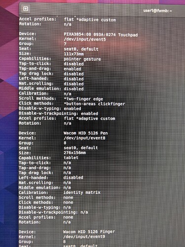
These connections were enough to get the touch screen controller to show up on the i2c bus in Linux, but the driver was not loaded so it was not usefull

In order to make it work I had to extract and decompile the ACPI tables on both the framework and my Lenovo yoga 720-15ikb. I then found the entry for the touch screen in the 720’s table and copped it into the decompiled framework’s table, making the necessary changes to the name of the I2C bus, setting the interrupt to the trackpad interrupt, and commenting out the trackpad. I then set grub to override the default ACPI table with my modified version

modifications made to the framework ACPI table

As long as trackpad interrupt is pulled low ether by connecting it to ground or by touching the trackpad during boot, the computer will communicate with the touch screen controller, load the driver, and work, at least on Linux. The screen I am using for testing is from a broken yoga 720-13ikb but, while its inverted because the replacement touch controller connected to it is from ebay and for slightly different machine, both the touch and stylus work corectly.

short demo video

Next steps:
First of all, I need to get the TS_INT pin on the eDP connector working so that I can still use the trackpad. I have looked through the schematic, embedded firmware, and decompiled ACPI table but I have not found any indication of what GPIO pin it is connected to. Furthermore, the I2C and 3VS_TS lines on the eDP connector seem to be non-functional. They go to 3.3V for about 2 seconds when the motherboard is turning on and then drop back to 0V. The reset and interrupt pins do not show this behavior and stay at 3.3V. I have tried connecting the TS_EN pin to ground and to 3VS_TS to no effect. Looking in the embedded firmware i2c definitions I don’t see an I2C port defined for the touch screen, leading me to believe that the pins are unconfigured or intentionally configured to turn off. If its feasible, I would like to make the pins work so that I would not need to solder to the motherboard and trackpad in the finished project. Once I figure out the eDP pins I will make a breakout board for the edp connector so that I can connect the display and touch controller simultaneously.

If you have any questions feel free to ask. If you know what the GPIO pin for TS_INT is, have any ideas for where to look for that information, or any idea how to get the TS I2C and 3VS pins to stay on, let me know.

12 Likes

I came onto the forum to make a post asking if anyone had tried something like this, awesome to see your progress so far! If you manage to figure something out in the end I’d love to try and build my own.

1 Like

I had some time this weekend and I managed to get the touch screen and trackpad working simultaneously. I was able to determine what GPIO pin TS_INT was connected to by connecting a square wave generator to the TS_INT pin and set it to produce a 0 to 3 V signal at 2 HZ. I then wrote a simple bash script that used the libgpiod utils to go through all 256 GPIO lines and, one at a time, print the state 10 times over 1 second. I watched it run and on GPIO line 12 I saw the square wave.

Further testing confirmed that pin 12 was in fact connected to the TS_INT pin on the eDP connector.

With this information I modified the ACPI table to re-enable the track pad and to change the touch screen interrupt to pin 12. Rebooting with the new table yielded a working trackpad and touch screen.

I still have no ideas for how to get the TS I2C pins on the eDP connector to work but now that the TS interrupt pin is enabled the trackpad and touch screen sharing an I2C bus, while not ideal, seems to work ok.

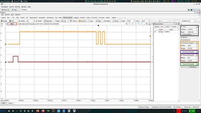
While I had everything powered on I also took the opportunity to look at the power provided on the eDP connector. The lower red plot is the 3VS_TS pin and the upper yellow plot is 3VS_EDP.

The 3VS_TS only comes on (and not even to 3.3v) for a few seconds when the computer is first powered on, so it is not usable for powering the touch screen, but the 3VS_EDP power seams to be on for the duration of the boot and only shuts off near the end of Linux booting so presumably when a display is connected it will stay at 3.3V for the entire time the computer is on.

I think the next step is to design and build a breakout board that will connect to the eDP connector on the motherboard and break out touch screen pins while passing through the display connections so that I can connect the display and touch controller at the same time.

6 Likes

Awesome project and writeup!

Looking forward to seeing your progress.

How did you reverse engineer the pinout? Did you watch the signals live in the original system or were you able to do it just from the digitizerd board?

To reverse engeneer the pinout I measured each pin with an osciliscope while the digitizer board was in the origonal system. I also measured the pins on the original system without the board connected in order to figure out what signals were sent by the computer to the board and what pins needed a pullup resistor. I do not think I could have figured out the pinout without the original system.

Furthermore, the modifications I made to the frameworks APCI table in order to get the OS to recognize the digitizer were only possible beacuse I could extract and decompile the APCI table from the origonal system.

1 Like

Thanks!

Out of interest, what are your plans re form factor? Do you plan to design a custom chassis?

I personally would be quite happy even with a pen-and-touch screen in the original framework clamshell form factor. I looked around for screens that would fit (13.5" 3:2) and there are not many. Originally I thought HP Dragonfly G3/4 would be good but they seem to not support pen input. The only ones I found so far that are 13.5" 3:2 (did not check the exact dimensions yet) are:

  • HP Dragonfly Folio G3
  • HP Spectre x360 14-EA (and possibly other submodels)

Another annoying thing is that most commonly you can buy laptop touchscreens without digitizer board, or you can get a whole laptop / whole lid, but then the display is often hard to separate from the lid (in 2-in-1s often glued in place and hard to remove without breaking it)…

Finding a touchscreen display that would work with the existing chassis would be awesome!

I am planing to make a 15in sized 2 in 1 with a custom chassis from machined aluminum and 3d printed parts. For ports I am planing to place usb-c hubs between the motherboard and outside edge.

I also ran into the issue of very few display options and lenovo was one of the only brand that I could find replacement displays without buying the whole lid.

For this project [Project&Inquiry] Framework 2-in-1 there is interest in finding a 13in touchscreen display that can be made to work with the framework so you might want to keep an eye on that as well.

1 Like

Also re disabling trackpad. Trackpad and touchscreen did not work together when sharing an interrupt line? Or you disabled it right away and did not even try that? Because in my experience, often it is possible to have two I2C devices sharing an interrupt line (albeit my experience is with much simpler devices such as GPIO expanders).

I never tried having them share an interrupt in software as I found that the trackpad its self actively drives the interrupt line high as well as low and because of that the interrupt pin on the touchscreen controller would only bring the voltage on the pin down ~2.5v when active which was not low enough to cause an interrupt. I though about putting a nor gate between the trackpad and the motherboard to allow for both to use the same interrupt but I got the interrupt pin on the eDP connector working first so I never explored that further.

1 Like

Sure, makes sense. I was wondering whether one could do this without messing around with the eDP cable (either using the existing one for a 40pin screen or buying an off-the-shelf 40-to-30 pin adapter) but this makes it seem more complicated.

If you can find a substitute for, or emulate, or don’t need the reset pin on the eDP connector you may be able to make it work without messing with the edp connector as there is another exposed interrupt pin on the camera connector that is used for the ambient light sensor. You probably have to disable the sensor if you assign it to the touch screen but it could be an option

I had been looking into that. But from the block diagram at the beginning it seems that the ALS I2C is connected to the EC only (so I presume the same would be true for the interrupt)…

Maybe a custom eDP adapter will be the easiest way in the end. There also seems to be another USB2 on the eDP that one could break out and use for something else internally…

That makes sense, I forgot that the EC has its own i2c capabilities.

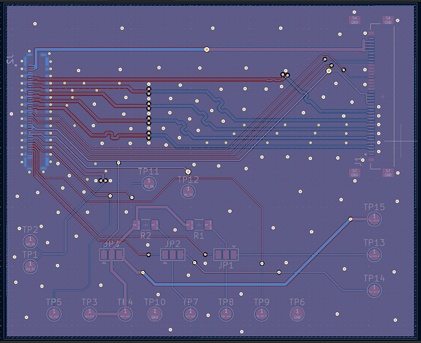
I think that an eDP breakout is likely the way to go and I recently finished the design for and ordered one that passes through the display signals to a noarmal eDP connector and breaks out all the touch signals to test pads.

I haven’t received it yet so I have no idea if it works but once I receive it, solder it together, and hopefully get it working, I will make a fourm post about it and finally get around to making a github repo

1 Like