i wanted to get a 1920x1200 panel for .. no particular reason?
1600p is a tiny touch too small. And I dont want to scale.
I found this .. the Dell NV160WUM-N42/N45. Will that work? For others, there’s also a 240Hz 1600p from Lenovo Y9000P, the NE160QDM-NZ3.
Both of these have the PCB on the back. So. No workie.
How about the Dell Inspiron 16 Plus 3072x1920 B160AN01.0 (NE160F8M-N41)?
The Huawei Matebook D16 NV160WUM-NH0/NH3.
Wrong connector.
Also Framework’s NE160QDM-NZ6 is bloody not that expensive. Damn that’s a fine display. huh.
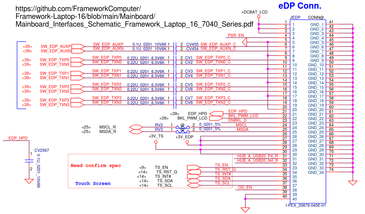
When I investigated this, it became apparent that the display-side connector is not standardized much, so you need to be very careful to match every pin from the laptop to the right pin on the display side. In the absence of any data sheets either from Framework or third-party displays this can be done loosely by checking where the grounds are in that connector, and if they match one of the common pinouts, hoping that it’s that one. (See example here)
I also got an impression that laptop-side pinout is also not really very standardized and that shuffling the pins from the laptop to a display is a common practice. Meaning that getting a different eDP cable from the one you already have in the laptop might shuffle the pins in a wrong way.
In addition to that, display connectors can have two pin pitches - 0.4mm and 0.5mm. Framework uses 0.4mm on both sides, so if the display you want has 0.5mm pin pitch, you’d need some kind of adapter to connect it to the laptop. DisplayPort is a very high speed interface and its signal wires need to have a certain electrical characteristic (impedance, I think) throughout all the way between source and display. Laptop and display manufacturers can agree on that number before production, but you’d then need to match it, incl. the adapter.
I am not an expert at all in those things, but this was enough for me to see that unless Framework works on a display option, it’d be really hard to come up with a viable display replacement myself.
And I didn’t mention that eDP can be 40-pin and 30-pin. That 40-pin eDP can be 2-lane or 4-lane. And that backlight power supply is also pretty much a thing specific for each display, so it might be that Framework has to update the BIOS to support each new display option by reading display’s EDID and then programming the backlight power supply for a particular panel.
PS. Again, I’m not an expert. I could be spouting 100% bullshit. Treat me as if you were reading an LLM’s output.
Framework’s “stock” is NE160QDM-NZ6. 4-lanes eDP, eDP 1.4b 40-pins. 4-lanes, 3.3V Typ. I-PEX. 12V (typ) voltage supply. No lamp information. But is 11S8P(11 group in series, 8 LED per group).
Yes. I think all of the options I mentioned are 40 pins.
NE160WUM-NX1 is 40 pin. eDP 1.4. HBR1. This is 4-lanes. 3.3V Typ.
This use the STM 0.5mm connector.
You also have the Innolux N160JME-GQA. eDP (4 lanes), eDP 1.4b, 40 pins. I-PEX connector. However its LED is 12S6P. It want 30.8V lamp, ± 2.2V. Could be close enough.
The B160UAK01.5, which is a touchscreen. However it’s 2-lanes eDP, and eDP 1.2, but still 40 pins, and 3.3V Typ. STM connector.
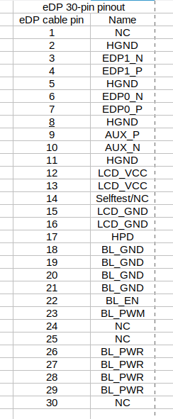
Left: 30-pin eDP, 2 lanes.
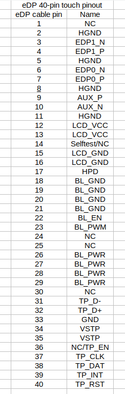
Mid: 40-pin eDP, 2 lanes, touch.
Note that 30-pin and 40-pin 2 lanes are basically the same thing.
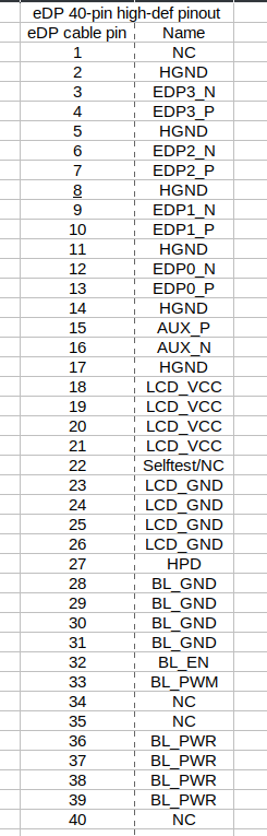
Right: 40-pin eDP, 4 lanes, no touch.
No point in having display side usb if the display doesn’t have usb.
They at least were on github at one point.
You also have to pay attention to the drive voltage for the backlight (or the el voltages in case of oled without internal regulators) and the signal levels for the misc io pins (3.3/1.8v)
I also want a 1920x1200 panel. Scaling doesn’t work for RDP and VNC. I see you’re looking at possible other panels. If you get one working, let me know please? This is the reason I haven’t bought a Framework.
Excellence. So all we need to do is to make a custom cable.
The 30-pin, as shown above, have the proper touch signaling. They just used that.
And from the schematic, you can plug in every display under the sun, though you will need different cables.
Most of the panels list input voltage as “5V to 21V”, which make sense, since they have onbaord regulators. Framework just pass it DCBAT, which is around .. 19V.
I guess it doesn’t, but it does raise questions like .. what do we use this USB for?
I guess for “just in case”.
If you are thinking of getting a 3rd party panel, then you should get the framework. The display removal and replacement is honestly oh so easy.
It’s actually so easy, you can do it in like, 5 minutes without turning off the laptop (though maybe don’t follow the last bit if you are swapping panels).
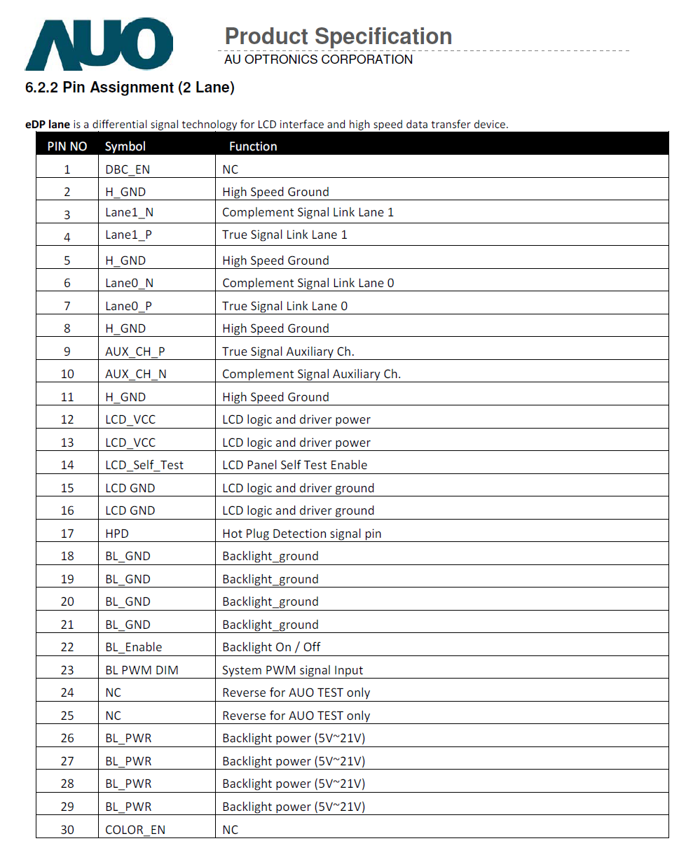
We also apparently have pinout.
From the looks of it, you can just buy .. any 4-lane display with “reverse” eDP connector of the “I-PEX 20682-040E-02” variety. Actually there are multiple I-PEX variety that shuold work, but you get the idea.
Having propper edp cables made is not quite as easy and especially not as cheap as it sounds last time I tried.
Would love to be proven wrong though.
A lot will just need different wiring but there are also some cases that’ll need level shifters and power convesion cirquitry so you can’t get away with “just” a cable for all of them.
To be ready in case they ever want a touch option, same with the exposed i2c that isn’t used. They are keeping their options open which is good.
I hope they managed to somehow squeeze 4 lanes of edp on the mainboard side 30pin in the case of the 12 cause 2 lane massively limits future display options which is kind of the opposite of what they have done with the 13 and 16.
Correct. I can try microsoldering, but I dont think I have sufficiently sturdy a hand. Would be great if Framework or someone small-batch some. Without custom cables you are limited to 40-pin 4-lane panels.
Then we can avoid such a case by just getting a different screen. There has to be one that meet both the “we” and the electrical/physical requirements. Maybe.
Touch, AFAIK, is usually through I2C. Primarily. What isn’t, however, is pen. Those are USB. Think like Wacom, or N-Trig. You have like two decades of stuff to flip through.
Or you can lump those two together and just use I2C. Which is probably what Framework’s 30 pin uses.
Also note that the connnector on the Framework github is for the main board side. The display side is “classified”, and, in fact, does not match Framework’s.
I do not know why they have to be so secretive, but I dont get to ask that question, I guess.
I thought both those two cables feed the display. Turns out only one of them is, and the other is for the lid.
Also yeah, Framework just give the display “DCBAT_LCD”, which is just 19VB.
You can’t really solder to those micro coax stuff at all, think there is a different process used to bond those.
In some cases there may not be that option. if there somehow showed up a fw13 sized oled screen that needed 1.8v io and external el drive those bits would be a lot easier for me to supply than a custom cable. My original plan for making the oled work in the t480s (after just plugging it in and blowing stuff up of course) was to add a custom pcb between the display side of the stock cable and the display that did the level shifting and el drive.
It CAN be done over usb too though so leaving the option available certainly doesn’t hurt, especially since framework doesn’t do entirely custom displays but uses modified versions of “other peoples” displays so having a bit of flexibility on the board allows them a wider sellection.
Classified may be a bit of a hard word there, just not public.
If it’s anything like on the 13 that isn’t 19V all the time (well in the case of the 13 that’s never unless it is running standalone but the 16 does have bypass mode so it can be 19V ish sometimes). We don’t have schematics but it’s probably just vbus behind a fuse so usually either vbat or or sightly above vbat (if the 16 also has the weird moving bus voltage thing going on it is probably even moving all the time XD).
Correct, but it meets the criteris of “5-21V”. We just need to find displays that have said requirements. Which, on Panelook, seem to be basically all of them.
In the GPD Win Max, it’s not (?) micro-coax, just straight wires. I imagine in the actual cable they are twisted together or something. Seems hand-soldered, then reinforced with epoxy.
You kinda just .. hand solder these. Much like Supermicro’s PCIe extension bits.
Not a bad idea. I’d do hot-air SMT over micro-solder those cables any day of week. Though you will need to find a place for such a PCB, and supply cables on both ends.
Are you sure? Micro coax does look like just wires at first glance. Then again the gpd may be small enough to just raw-dog direct wires. Doubt it though.
Since I am only looking for oled that isn’t a problem as there will be plenty of space behind the display XD. For lcds you’ll have to get more creative but it’s probably still possible, especially with flex and semi flex pcbs becoming somewhat affordable now.
Damn.
And also, yeah OLEDs usually come with added circuitry for driving. LCDs not really. On the Hp I took apart (and cracked the $250 panel, great Hinge Problem), it has a PCB glued to the back with power bits.
I am thinking the main (laptop chassis side) compartment for the PCB, its a bit more roomy. But nothing is preventing you from removing the bezel for a 5mm display, lol.
Ok, so they are micro-coax, But this look like doable by hand.
Lcds certainly seem to have less “adventurous” pinouts. Oleds seem to come in 2 varieties power wise: built in driving circuitry you can just feed vbat and ones that want you to provide a positive and negative regulated voltage directly.
Advantage to the second option is likely that you can make the display even thinner and shift some of the cost to the board.
Evidently not my hands but the cable I took apart trying rewire didn’t seem to have been soldered, looked more like spot welded or something.
You’ve already replaced one with a 1920x1200? If so, do you have links to everything you purchased? I’m in the U.S. Did you have to solder? My soldering skills are a bit rusty and never with anything that small.
I’ve been searching for panels but I’m not finding anything with that connector in the listing, only by the model of the laptop they’re compatible with.
Given a choice of panels:
Touch doesn’t matter.
60hz or above is fine.
Contrast and color accuracy I do care about. Then power consumption. It’s not that critical though. Any modern panel should be pretty good and I remember laptops from 25 years ago. And desktops from 40 years ago.
Could have been spot welded, or maybe crimped, but probably with individual pins that are fitted into the connector body after being fitted to the cable.
Any form of micro-coax will almost certainly have been fitted to the cable before being fitted to the connector body. That is the only way to get proper connection to both the centre and shield wires.