Sure, I’ll get working on it ![]()
According to this, Type B is the larger of the two sizes. Not many ideas on what can be achieved with the space savings of a smaller card, honestly.
I guess, the smaller card (82x70mm) will not fit if the connector is rotated 90 degrees, i.e. parallel to the interposer contacts. Because from your last 3D screenshot it’s apparent that the power components are interfering with the thermal pipe’s route to the right fan, and rotating the card could be a solution to that.
Whoops that’s my mistake, sorry. The model shows the larger of the two cards, (Type B then i presume), and yes the coils are kind of in the way. Honestly its an annoying position to be in because there’s so much wasted space between the PCB and card:

There’s absolutely enough room for heat pipes, if the die wasn’t on the top… Honestly the two best ideas I’ve had you’ve already pointed out - either it needs to be inline, (custom connector? ![]() ), or it needs to be sandwiched and hence upside down. I’m going to start looking for a connector now just before V0.3 goes live with a couple of improvements.
), or it needs to be sandwiched and hence upside down. I’m going to start looking for a connector now just before V0.3 goes live with a couple of improvements.
1 Like
Interestingly enough, this is the same sequence of exploration we did in 2022 when we started developing Framework Laptop 16, along with the same conclusion that the only plausible solution is having the GPU PCB be at the same Z plane as the Mainboard, and for MXM, that requiring both a lot of space and an entirely custom connector.
8 Likes
I thought I’d be smart and look for a 0.5mm pitch connector without the key, so with 320+ pins. But at Mouser max pins is 300, unfortunately
Crazy idea. What if… We put two unkeyed and open-ended connectors… next to each other.
If you find one, sure ![]() But I’d say the dead zone on the connector margins will be longer than 3 pin gap in the MXM key… unless you sand down one side of each connector (which makes the whole process much less reproduceable).
But I’d say the dead zone on the connector margins will be longer than 3 pin gap in the MXM key… unless you sand down one side of each connector (which makes the whole process much less reproduceable).
Ohhh. Hadn’t even considered that, that was unintelligent of me. I think our options may now be reduced to either a daughter board or a rigid/flex pcb. Just concerned that it’ll skyrocket in price.
1 Like
V0.3
Thing’s I’ve fixed:
- All PCIE lanes now have a suitable ground return path
- Power traces thickened and vias close to the framework interposer shrunk to save space
- General neatness improvements

I think this may be the last fully rigid design. I’m going to give rigid/flex a shot for V0.4 to keep the footprint lower, but this will be a huge redesign and I’m getting my GCSE results back tomorrow so I may take a while. If anyone can find a straddle connector or some other inventive solution in the meantime it would be very helpful.
5 Likes
Oh, last thing: I’ve sent an email to X-VISION, (who make the 40 series MXM gpus), to check up on the state of whether we’ll be getting any 50 series mobile cards.
5 Likes
I am hereby participating.
Biggest update so far, V0.4:
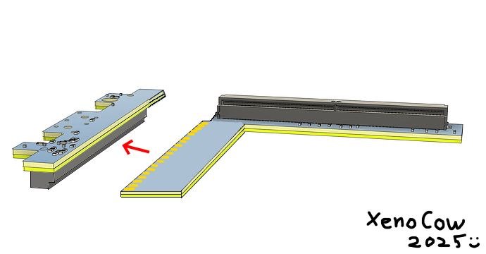
- Complete redesign moving from a rigid board design to FPC
This lets us bend the whole assembly without having to bother with fiddly FPC cables. It’s a six layer FPC board, (minimum for PCIE standard), so it could end up being obscenely expensive, but it’s a solution none the less! This will make the assembly much less bulky, only needing to lower the Z height of the GPU enclosure in one spot where the MXM connector is.
Now we can start on a thermal solution with much more room.

7 Likes
FPC design? You absolute madlad. ![]()
I love this thread, can’t wait to see prototypes! ![]()
6 Likes
I am almost falling over. I don’t say this lightly, but seriously, someone in the community posting daily updates on a replaceable GPU in a replaceable notebook expansion bay, while the CEO of the company is casually chipping in. This is peak tech community.
Nvidia, if you see this, doing stuff like this could help making GPU launches a bit less prone to hardware issues.
PS: to add a bit more detail, at least more community surveys for Desktop GPU launches would already help (e.g. would you like to monitor all your temperatures in a GPU? Would you like to play old games with your GPU? etc.). I think it would be really advantageous..
3 Likes
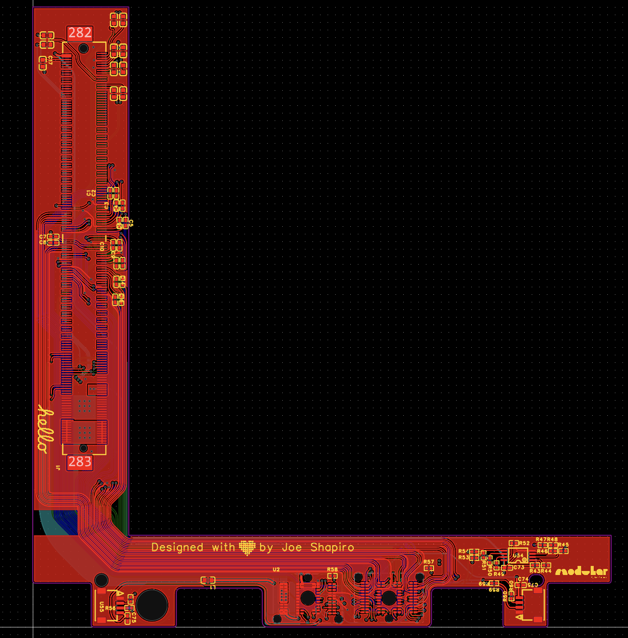
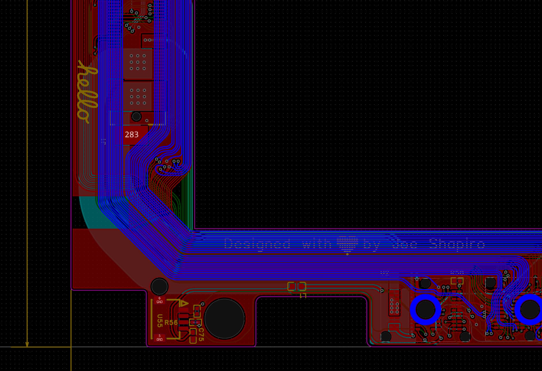
V0.4 is up on Github now. So there’s good news and bad news. The good news is that I think this idea will work, the bad news is that PCBWay’s online quote provider is current claiming that it will cost me $600 for one board. Which unfortunately is uhh… a bit more than I think is reasonable. I’ve still submitted it for review in the hopes that the online quote is just going haywire, but it may be that we have to look at other options. Crucially, we need four layers of flex pcb at a minimum to pass all the PCIE, power, and other signals to the MXM connector, but this does currently leave two grounding planes of the six layer board redundant and possible to remove. This would be a complete breach of the PCIE standard, (again supposed to be a minimum of eight layers to reduce signal noise), and I’ve got absolutely no idea if it would work, but a four layer flex board is manufacturable by JLCPCB which could be much more economical. I’m still hoping that an EE will stumble across this thread and tell me how far I can push abusing the PCIE lanes, but until then it may just be trial and error. Take a look at the screenshots below to understand why we need four layers minimum.
TOP, (PCIE signals)

LAYER 2, (ground plane currently)
LAYER 3, (Auxiliary signals and output to display):

LAYER 4, (power and ground):

LAYER 5, (ground plane)
BOTTOM, (other PCIE signals):
Ideas, anyone?
1 Like
I don’t know anything about PCB design really, but to cut down on cost a little instead of this multi-height board, could you not instead design two separate PCBs that are stacked on top of one another, either via some kind of socket or a more permanent soldiered bridge of sorts?
I’m imagining a large grid of pins and sockets… or attaching the two together with yet another PCIE connector. Something like this:
4 Likes
This is unbelievably smart. Like genuinely this is an incredible idea. We could totally use edge connectors! More power delivery, and even then modularity!!! You could buy one, “base” card, (the top section), and then slot in either an MXM card, or say, more USB, or an occulink port! And if you put the EEPROM on the base card then the modular extentions wouldn’t even need to be that expensive or complex! Thank you so much - this is amazing.
6 Likes

About to order a 740M mxm card used from the UK as a test bed. PCIE 4.0 compatible, but only 8 lanes. Power draw will be a bit less then what we’ll be seeing from 40 series cards, but it’s cheap and easy for the time being and should be fairly representative of what we can expect from other cards.. Anyone got any other ideas/foreseeable issues before I place the order?
4 Likes
The specs say it’s PCIe 3.0, but I think it’s even better to have it like that instead of starting with PCIe 4.0 right away so that the PCIe 4.0 signal issues do not compound with any other issues the prototype might have.
1 Like