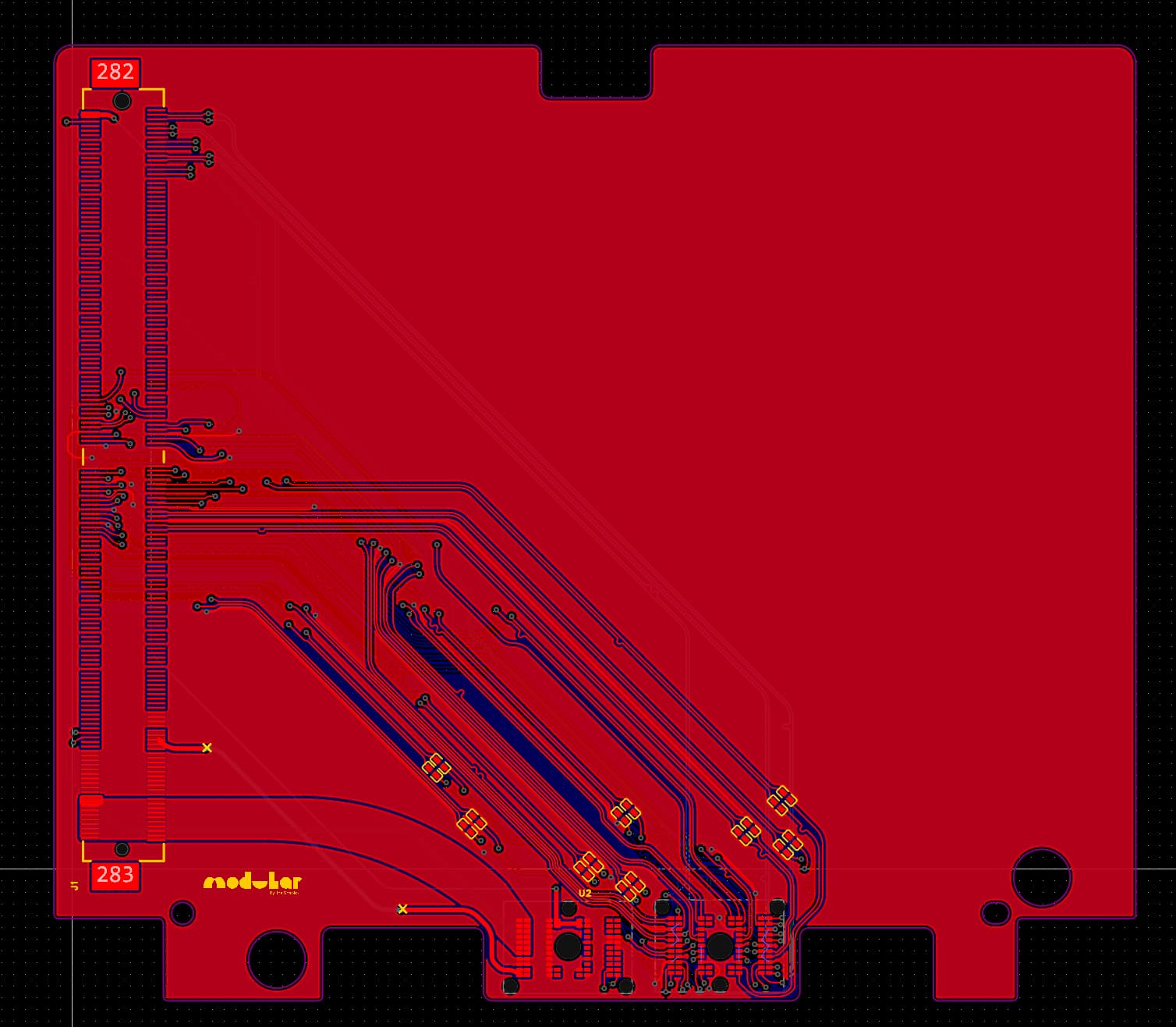
Hey all. Looking for some help developing a Framework 16 to MXM gpu adapter. I’ve sketched up a really early design, (see PCB), but am still missing the intricacies of the PCIE standard. I was hoping that someone might take a look at it and work with me to fix any obviously immediate issues. I don’t actually have access to a Framework 16 to test this on, but it feels like something that could lay the foundation for improvments. If we can get something like this working it would completely change the graphics game - and open up the world of Nvidia for Framework, (with 4090 mobile MXM modules already available).
I can’t help but if I could get a layman explination of how this would work I’d appreciate it. I understand the MXM adapter lets you use mobile GPU’s in another system, but is it really that easy? it seems like something Nvidia would assassinate people over
Sure! I have a fairly basic understanding as well but I’ll do my best. First of all though you might want to take a look at this hackaday article which I found really useful.
Okay: MXM.
To my understanding, It’s essentially like the PCIE slot that you find in a desktop computer but just repackaged into a more efficient form factor. The MXM slot provides power for the module, (which basically just has the VRAM and GPU die on it), along with PCIE lanes and some extra fun stuff which for the moment I’m not bothering with integrating. It was shockingly simple to integrate with the way that Framework have set up the expansion bay system - props to everyone on the team who designed it - as it was literally just a matter of hooking up the PCIE connections and some timing signals.
MXM has its limitations though, and especially in this form factor. It’s quite bulky for the scale of a laptop, and some cards which claim to be, “MXM” compatible are actually just repackaged with the same connector.
Because the FW16 only provides eight PCIE lanes, that’s the max that I’m able to hook up to the card, but in reality this shouldn’t make a massive difference. In terms of Nvidia: I thought so too initially but then took a look at the occulink thread which seems to have found lots of success with it. If you haven’t already read it then people are using the M.2 ports on the FW16 to wire to a PCIE adapter, and run Nvidia cards from that seemingly without issue.
This should actually be less janky than lots of those setups, using eight PCIE lanes instead of four and with more precisely tuned traces. I guess I’ll have to wait and test it at some point in the far future, unless anyone else has other ideas.
Just a note that the main limitation is going to be mechanical. Recent MXM modules are both mechanically much larger than the original MXM spec and require larger thermal solutions.
Indeed the Clevo MXM cards are wider than the MXM slot.
I also saw a company called X-vision selling new MXM cards within the normal footprint.
But then I agree, the cooling system must not be overlooked - every MXM can have the chip in a different place - how to design a set of heat pipes and/or vapor chamber that would fit a good number of those? Especially the future ones.
Another possible concern is power management - how do you tell the GPU to not draw more than 200W overall as that’s how much the interposer can deliver (at max voltage of 20V, I think). And probably EC/BIOS needs to also get involved to balance the rest of the power properly…?
But overall if this solution would be possible and would support at least some subset of cards, it would be really cool as this would make upgradeability so much more viable and worthwhile
That’s actually an interesting point. Presumably the card asks for power through the PCIE control lanes? But maybe you can set limits on the cards through their bios settings.
In terms of cooling I’m not quite sure what the best solution is - maybe you’d just have to build a separate solution for each mxm module.
Found this article that says that the standard defines GPIO pins for telling the card how much power to pull, and that the placement of the chip and holes for cooler mount is also in a standard, so there’s hope for standard implementations to fit a single cooler.
At the bottom of the article they link to a prototype for Framework 16,which might be of use to you, or you might even collaborate with the person who made the prototype
Woah that’s really helpful. I’d actually linked the article above in response to someone else but had no idea that someone had actually started designing one - thanks! It’s been a challenge to find an mxm connector that’s low profile enough to hold the card at a level where a cooling solution could be integrated above it. I’m not quite sure what the best way to explain is… On another note, could you, (@nrp ?) clear up what is meant in the Framework Expansion Bay electrical repo when it says:
Does this just mean that I need to link up the ID0 line to ADC, (7-20v)? Or is there some kind of EC that I need to integrate on the PCB to get the framework to provide power?
Following on from this, I’ve had a look at the reference designs provided at the end of that article, which seems to leave ID0 and ID1 lines connected.
Final question, (I promise), to anyone who knows more about this then me - is it literally as simple as just wiring up the PCIE interface to get a connection with the computer? Or is there some kind of handshake necessary between the mainboard and expansion slot?
I know for sure that the expansion board needs to have an EEPROM chip that the EC on the mobo reads to determine which expansion board type it is and configures the computer accordingly. Here’s the repo which generates the contents of that EEPROM. There are two types - dGPU and dual M.2 boards (repo refers to them as GPU and SSD). I don’t know what EC does differently for those other than enable bifurcation for the dual M.2 board.
You would probably end up reading EC source yourself or teaming up with @James3 to create EC firmware that supports this new card, as EC does all the configuration of the mainboard to work with the expansion bay module.
There are also other EC_GPIO pins on the board connector which control power sequencing and most likely need to be functional for the GPU to work correctly. E.g. 62-GPIO0_EC; 63-GPIO1_EC; ID0; etc…
I wonder if it may be easier to create a bigger enclosure with more z-height for the GPUs? Though I wonder how much deeper can the expansion bay PCB sit before the interposer stops reaching the contact pads on it…
PS: I’m writing my posts with the intention to orient you as much as I’m able to withing the available information. My knowledge, though, is not particularly deep in those topics, so while I can point you in some directions, I cannot really offer a lot of substance. Sorry for that
Ooo okay. It’s pretty incredible that so much of this is open source. I’ll take a look at the repo now.
In terms of the enclosure though, I had exactly the same thought. The glaring issue though, (as you’ve identified), is the interposer, which I’d be nervous about making significantly lower. Am I right in thinking that it’s a flex cable though? So maybe you could pull it closer to the mainboard to compensate for it being lower. The other option is of course a daughter board raised above the PCIE holding the MXM card, which could then give us much more freedom in the position. I’m only worried about passing really high-frequency and precision length-tuned PCIE traces through a whole bunch of connectors.
It is an extremely short flex cable, yes. It has a bit of a bend, so it can stretch a bit.
I am not competent in those things, but intuitively I agree, increasing complexity is probably not the right approach.
One idea I just got (if the enclosure is custom) is to invert the order of things. Imagine that the pads for the interposer are on the other side of the board from the MXM connector. Then from top to bottom you get:
Interposer
Framework MXM adapter board
MXM GPU
Cooling solution
Expansion bay module shell
Then the interposer pads are always topmost and the z-height is unconstrained to accommodate the normal MXM connector plus cooler of any beefiness (and jankiness)
Integrated EEPROM controller. This is based on the dual m.2 design found on FW’s repo. I used it to check lots of the other connections and I’m now actually pretty sure that this design could work.
As it turns out, the ID lines I asked about earlier just need to be pulled to ground with 330k resistors, so that’s sorted as well
I’ve designed in the fan headers and wired them up to the interconnect.
Added 0.1uF capacitors to the EDP lines which I’ve been told is correct? There’s not much info on how to actually design to the EDP specifications but I’ve been told that it works soo…
Added PCIE REFCLK+ and REFCLK- lines which for some reason were missing before
Added panel and backlight controls with the interconnect
Fixed unclear labeling on the symbol for the Framework interposer in the PCB schematic
Amended the SCL and SDA lines which read from the EEPROM
Moved around some traces to facilitate new connections.
The flipping idea seems like a great one! It’s always wise to leave some space for jank, but I’d be concerned about making it unnecessarily bulky. What I’d actually like to do, (though I don’t think there’s currently an MXM connector that actually works like this), is to have the GPU upside down and then put the cooling solution sandwitched between the board I’ve designed and the GPU. Of course, if this isn’t possible I may really be left with no choice but to redesign the whole thing upside down. It would be a bit of a pain though. I’ll attach two images here of the new schematic and PCB.
In terms of reducing Z-height, had an idea and found an edge connector for MXM - the JAE MM70-314-310B2-2-R500. It’s no longer produced but can be had on Ebay for a bit of money. Of course, having the edge connector would mean you won’t have much PCB to route all the stuff through, etc etc.
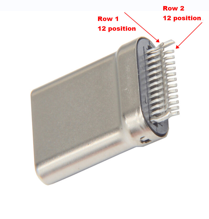
Hmm great idea. If it wasn’t obsolete I’d redesign it immediately, but I don’t think many other people are going to be willing to spend that much on an adapter. What I actually wanted to find is a, “straddle” type connector, like many USB-C plugs:
The issue isn’t actually enough space on the X or Y axis, as I could probably redesign it, (again), if I could find a connector that would let me hold the MXM card at the same Z height as the interposer.
Sorry I should maybe make it clear about how straddle connectors work: they sandwich the PCB between them and have pins on either side, (which would actually make routing easier as well.
Oh wait the link you sent is for 10 connectors?! that kind of changes things. If the prototype works and there’s interest from the community I guess we could do a batch?
I’m definitely down to participate, but only if the cooling solution question is addressed. I.e. there’s a way to get the card cooled once it’s installed