Correct. I’m no Electrical Engineer but since the CH341A works I’d say its a hardware issue somewhere.
1 Like
Just seen this - will do after writing this. Honestly I’m getting quite confused. There’s nothing obviously wrong here.
- We’re getting power
- Write protect is pulled to ground with an 100k resistor, checked with a multimeter.
- The SCL and SDA pins are definitely connected to the right pads:
- Voltage on the A0, A1 and A2 pins are all definitely grounded. I’ll check WP as well but it shouldn’t even be an issue in this case as I’m only trying to read from the EEPROM, not write to it.


Where else could the issues be?
I am right in thinking that the SCL and SDA lines should be pulled up with 4.7k resistors to 3.3V right? They’re literally the only other components between the EEPROM itself and the Framework MB.

I’ll be right back once I’ve taken a look at what the voltage on the SDA line does.
From those pictures.
Pin 7 (of U54), WP appears to be connected, via R49 to VCC.
Yes, the SDA, SDL can have 4.7K pull ups.
I assume R54 and R55 is zero Ohm.
Yep I’m aware. There are two resistors listed in the datasheet tied to WP, one 100k pulling to ground and the other 100k pulling to VCC. I’ve removed the one pulling to VCC in order to disable WP - on this physical board consider it an NC
Can you take a close up photo of the actual PCB board, so I can see which resistors are populated, and all 8 pins of the EEPROM. I am guessing there is just some simple mistake, but we are missing it, as I don’t have the PCB in front of me.
Sure:

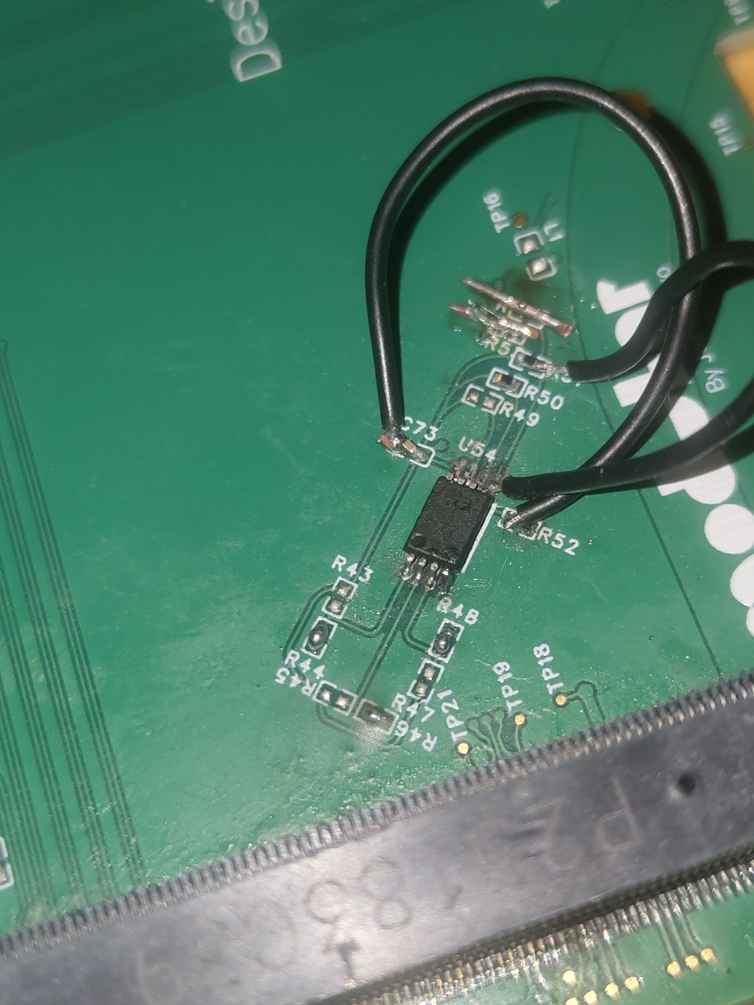
Here’s an explanation of some of the madness:
Bridged pins at the top of the PCB are for A1 A2 and A3. Literally just a few minutes ago I managed to screw up and rip the SDA pin from the PCB so I’ve temporarily fixed it with the black wire from the ripped pin to the resistor and rest of the SDA line. I’ve essentially just bypassed the trace. The other black wire is from write protect to ground because WP kept reading 3.3v even with an 100k resistor pulling to ground, (and if anyone can explain to me how this is remotely possible that would be great), but this is now failing my continuity check between 3.3v and ground. Hope this helps, and I’m happy to send more pictures if it helps. I’ll probably rebuild everything on a fresh PCB tmmr but this is the best I can do for tonight.
1 Like
I have looked at the EC source code.
It appears that the EEPROM is read only once at boot up. (of the EC, not the CPU)
After that, only cached values are read.
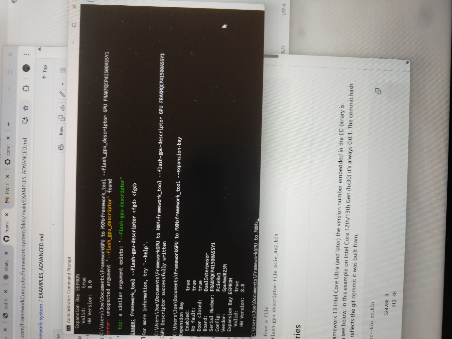
So, those “framework_tool” might not be doing what you intended them to do.
So, it might not be reading the EEPROM chip at all.
Did you see any movement of voltage on the SDA line at all?
To force an EC reboot, power off the laptop, remove PSU, leave for 60 seconds, plug PSU back in and power on.
Simply rebooting the PC does not reboot the EC.
Note: I might be wrong on the above. Please ignore for now.
Looking at your picture, it might just be a trick of the light, but is pin 4 (GND) connected to anything? It looks a bit open circuit in the picture.
1 Like
It should still be able to write to it though no? The continuity check failed before I had a chance to read the SDA lines and I had to call it quits for the night, (11:30 pm British time here). I’ll take another look at it tomorrow and thanks so much for all your help so far.
Sorry I meant to say as well:
Definitely connected to ground I think. I’ll check the solder joint again though tommorow.
2 Likes
It is actually pretty impressive, that you have got this far without an oscilloscope.
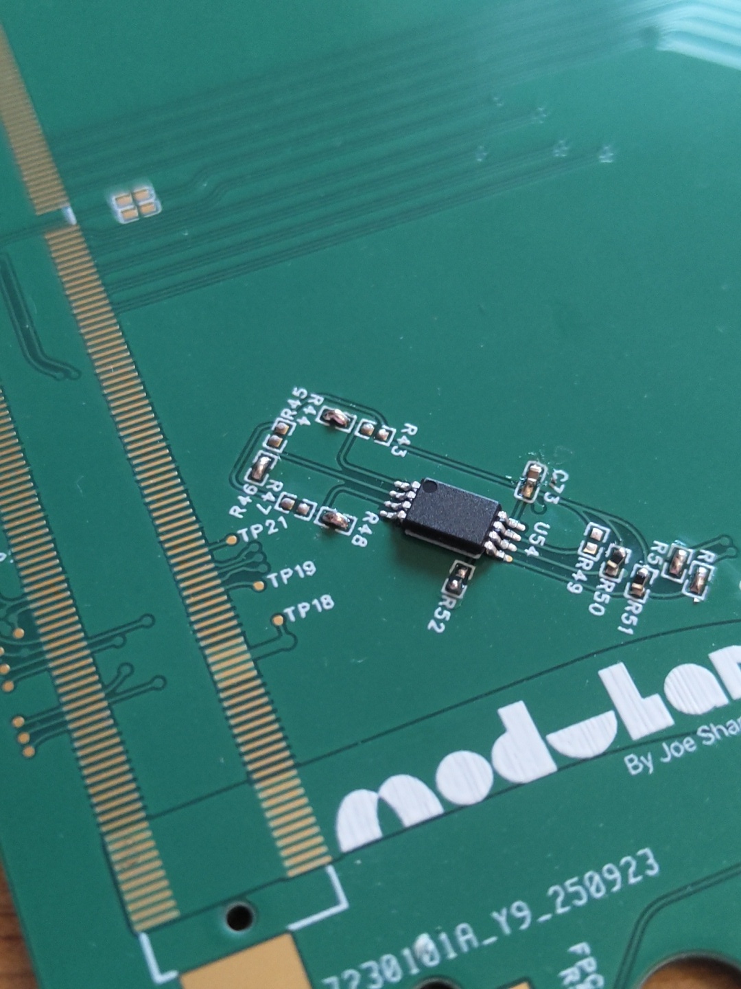
Hallo again. I’ve completely built another board from the ground up with completely fresh components, just to be sure. Here are the checks it’s passed:
- No shorts between 3.3v and ground
- Both power resistors reading 330k, (see schematics)
- A1, A2 and A0 are all pulled hard to ground.
- Full continuity between SDA, SCL and the interposer connection
- Reading 4.71 and 4.67 on SDA/SCL resistors respectively
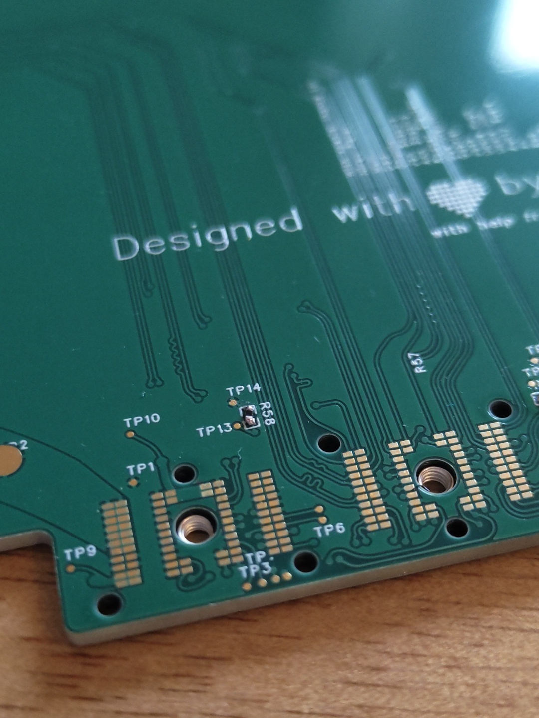
I also haven’t put on any other than necessary components just to be safe. See pictures below while I boot up the MB.


5 Likes
Hi,
Here is an interested part of a schematic:
- It uses a different EEPROM chip.
- The SDA/SCL should go between 0 and VCC. You have VCC at 3.3V, so why is the SDA/SCL above 3.3V ??? 4.71 and 4.67
I cannot find any schematics that say what the SDA/SCL range is supposed to be coming from the FW16 mainboard.
Which pins on the inter-poser are you connecting them to?
Which PCB design program are you using ?
2 Likes
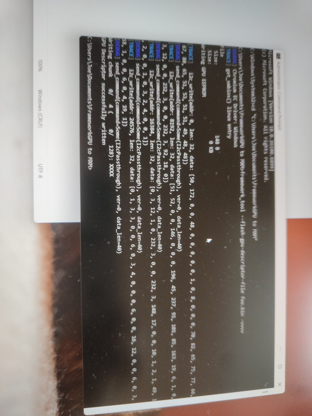
It worked!!! Why? I don’t know!
6 Likes
I’m working from the latest reference schematic, which I believe was posted after that, and the 4.71 and 4.67 in turn are the resistance readings of the resistors on the SCL and SDA lines, not voltages
1 Like
Anyway, the new board seems to have fixed all the problems, (hooray), which means now we just have to plug in the GPU and test it…
6 Likes

Do you have points on the board to attach the fan power,rpm sensor to?
I see you have one fan there temporarily powered from somewhere else.