This is a wiki post, you can add to or enhance its contents by pressing the
Editbutton at the bottom of the post.
Edit: Since the start of the thread many superior solutions were posted by community members. Here’s the list:
| User | Notable features | Picture | New parts used | Caveats | Post |
|---|---|---|---|---|---|
| @Gmanny | cable m.2 - oculink oculink - pcie | Hole in the back of the laptop with a cable sticking out of it. | #1 | ||
| @Maciej_Godek | OcuLink port is inside the laptop with cable fixed with capton tape. | Resistance/friction when fitting expansion module inside the chassis. Potential space and heat issues with adding a second m.2 ssd. | #28 | ||
| @Gu_tally | Tries to combine two m.2 ports into a single 8-lane interface, but fails. | ribbon m.2 - oculink adapter, e.g. from here or here or here. | (Unverified explanation by @Gmanny) Dual M.2 PCB contains EEPROM that asks the CPU to bifurcate the GPU interface into 2x4 PCIe ports. Combining those back is not possible since they have separate timing signals in bifurcated mode. Custom PCB with custom EEPROM is needed to tell CPU not to bifurcate the GPU interface. | #31, #36 | |
| @Morkale | Uses a 3D-printed part to hold the port in-place and close up the back of the laptop. You can see links to 3D models in the post | ribbon m.2 - oculink adapter | It’s pretty close to perfect. Only thing is you still need to carefully fold the ribbon and make sure it’s flat enough not to rub agains the body of the laptop when inserting the expansion bay shell into the laptop. Oh, and another thing, you can receive different M.2-OcuLink adapters which would mean the fitment with the 3D print might be different, see post #56. There’s also a different 3D model to support M.2-OcuLink adapters with different hole arrangements by @Kyle_Tuck in post #60. | #49 |
TODO: Convert some of the details from different solutions into a guide with options.
Original post
Well, why wouldn’t it really, but I was curious.
I pre-ordered Josh Cook’s OcuLink expansion module, and wanted to have something to test it when it arrives, but didn’t want to invest too much money before I know the solution works and suits me, so I ordered these parts:
- 1-meter variant of this cable. (18 EUR)
- 15cm variant of this M.2 to OcuLink 4i adapter. (12 EUR) I liked it because it supports 2230 length and has relatively flexible part, which I initially intended to route from the secondary SSD slot on the motherboard.
- The cheapest OcuLink 4i to PCIe board I could find. (16 EUR)
Once the dual M.2 PCB from Framework went on sale, I got it as well, and stuck the M.2 to OcuLink 4i adapter into it with the OcuLink port sticking out the back. The thickness of M.2 PCB was too high for the included retention screws, so I had to file down the PCB at the retention screw location a lil bit, checking that I didn’t short any layers. Instead of doing that, you can use one of the other fasteners that come with the expansion bay shell to hold the M.2 PCB in place, see this post below. (If you do opt to file down the M.2 PCB, be sure to do the filing at a different location than your laptop because you’ll produce a lot of fine copper dust and you don’t want it getting into your laptop. Wipe the PCB after filing with a cloth damp with alcohol as well.)
To make the eGPU appear in the device manager I had to enable power to the GPU via the switch on the OcuLink 4i to PCIe board couple seconds before pressing the laptops power button.
- Then I downloaded latest Nvidia drivers, installed them
- Restarted to see the eGPU showing error 43 in device manager
- Ran the error 43 fix script
And that’s it, the GPU outputs to my 4k60 screen no problem.
I didn’t run any performance benchmarks, if anyone’s curious of any numbers, I can do this. But I suspect it’s going to be similar to prior benchmarks of people attaching the eGPU directly to the M.2 slot on the motherboard (see the whole thread there!).
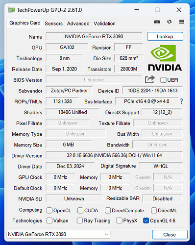
I also did this with a PCIe gen3 GPU, and I don’t have any gen4 devices to test, unfortunately, so can’t tell how good it would be at negotiating higher link speeds.
Since the M.2 to OcuLink adapter I linked even has retention screw holes, I can see it being possible to 3D-print a holder for it that would make the port flush with the laptop’s rear wall and would look quite decent.
Photos:
Testing how fully internal connector could look like:
Cable is probably not flat enough, and it couldn’t be situated like that. It’s not bendable too much, but I would try forming it into a shape that fits next.


