I got curious and wanted to try using the macropad by itself, but it doesn’t seem like the the laptop would let me.
Is there a limitation on the USB that the keyboard must be present for the input cover to turn on?
I got curious and wanted to try using the macropad by itself, but it doesn’t seem like the the laptop would let me.
Is there a limitation on the USB that the keyboard must be present for the input cover to turn on?
When it doesn’t detect all spots (excluding touchpad spacers) filled it disables power to everything to avoid risk of shorts or other potential issues. I believe that protection feature can be disabled in the BIOS, but it is recommended to leave it enabled.
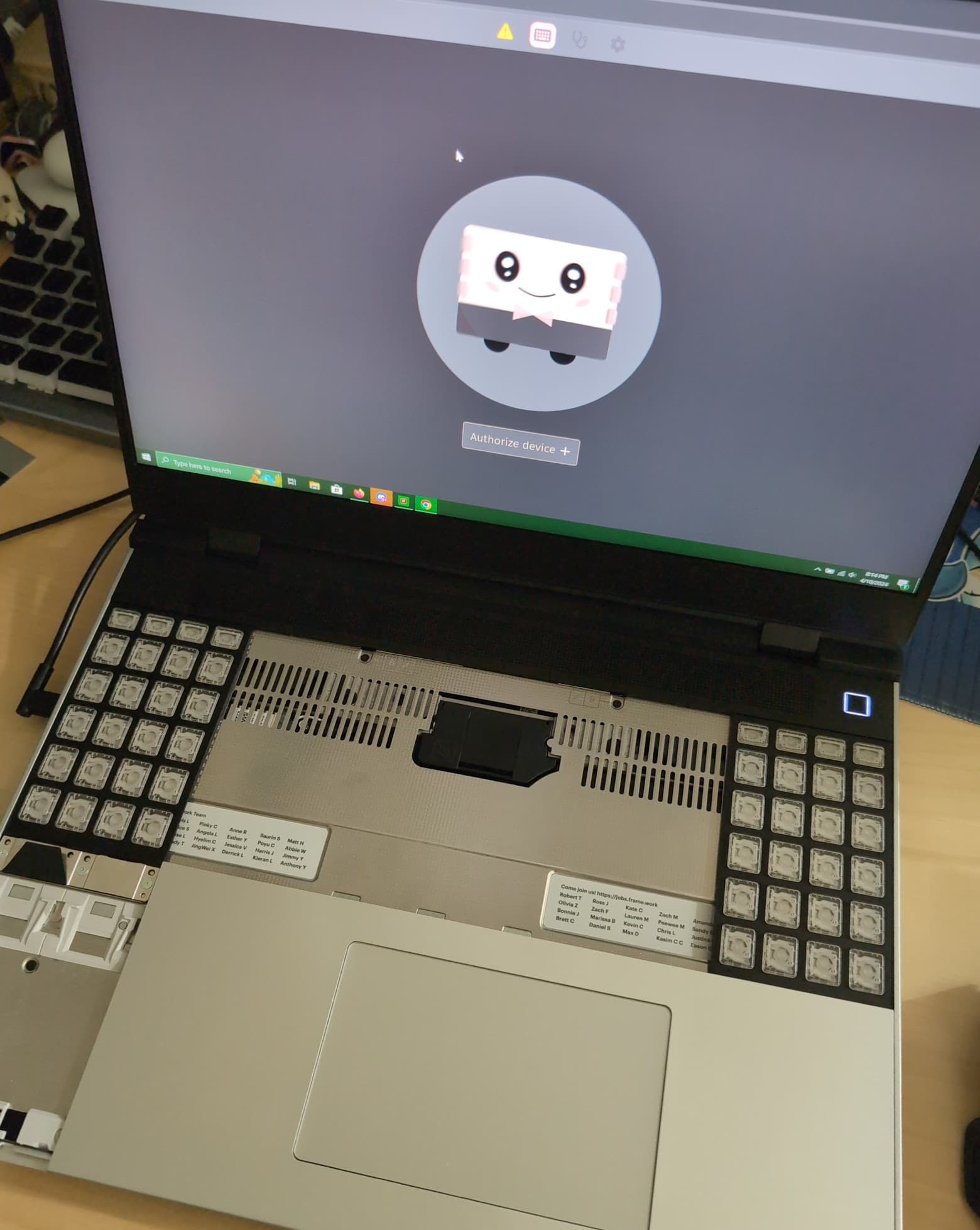
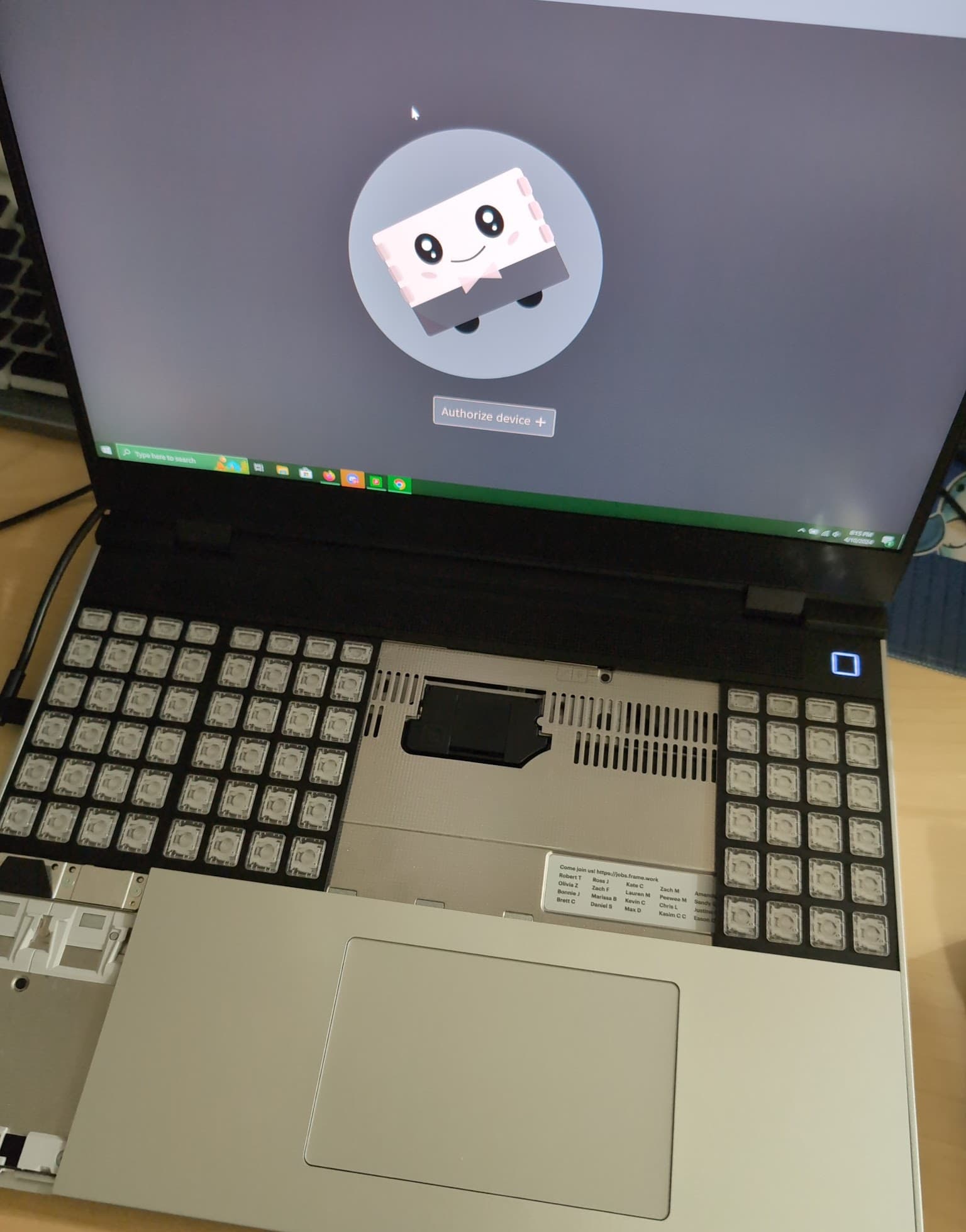
I just tried to fill it with a combo of LED matrix, blank spacer + another macropad, and it still doesn’t work.
From what I observed, the third set of pogo pins do not have the guide posts that keep the spacers in place, and do not sit happily. The only connector that works on the third pin are the on the keyboard. ![]()
Hi @mrwm,
Kudos to you for trying go ALL Macropad ALL the time! I admit it is a unique look. Now you just need the matrix displays on the lower slots and it would look like a futuristic speak-N-spell.
In addition to the preservation of NOT shorting out the midplate; I would like to think it is also an Anti-Cat mode. See if they keyboard is not there, a kitty would love to curl up on the nice warm midplate when nobody is looking. All that fur is ripe for lots of static and BZZT! Huh, no more input at all from the midplate I wonder what is wrong?
With the keyboard in place there is decent protection from the static generating curling up or stretching out after a nap in a warm spot on top of the FW16.
(Full disclosure, I do not own and never have owned cats; though I have cared for many of them for friends while away)
It might still consider the input deck to have open areas. You might have to flip the BIOS setting to enable powering the input deck.
Welp, I’ll update either tomorrow or later, after I test out other combinations of input modules without the keyboard to see which combo works without keyboard. I was hoping to use three macro pads as an ortho keyboard.
I read that framework tested with two macropad modules, so I assumed that it would work, but as the pictures shown above… it does not. ![]()
Out of curiosity… why do you want to do this?
Macropads? Macropads!
Not sure if you have seen this.
Late update, but here are the findings I made messing with the combos of input modules on my FW16…
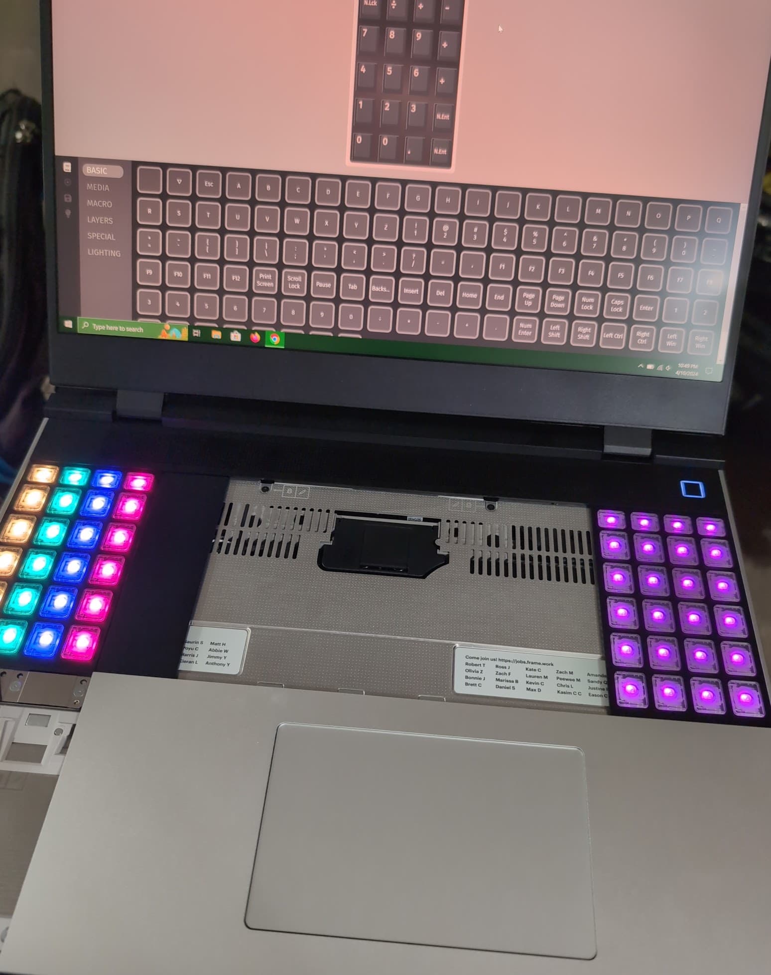
TL;DR: It is technically possible to have 3 macropads working, but the macropad in the middle blocks the touchpad from connecting to the input deck.
So why do I want to have three macropads on my FW16? I was curious and wanted to see if it would be possible to use it as an alternate to a semi ortho keyboard layout.
My arsenal:
In a fancy table format…
input module name (# in width)macropad (2) | LED matrix (1)E denotes emptyC denotes covered by the macropad| Success? | Input module (Left) | Input module (Second Left) | Input module (Second right) | Input module (Right) |
|---|---|---|---|---|
| macropad (2) | macropad (2) | macropad (2) | C | |
| macropad (2) | E | macropad (2) | C | |
| E | E | macropad (2) | C | |
| E | E | E | LED Matrix (1) | |
| macropad (2) | C | Blank spacer (1) | LED Matrix (1) | |
| macropad (2) | LED matrix (1) | macropad (2) | C | |
| Blank spacer (1) | macropad (2) | macropad (2) | C |
What works: Any combo that adds up to (3) on the left, and any combo that adds up to (2) on the right.
While I didn’t test all the combo available, I had a general idea of what the criteria needed for the input deck modules to work.
As pointed out in the replies above (Thanks @MJ1 & @Kyle_Reis), the input deck needs to have all the USB connectors populated, along with the touchpad connected on any of the middle three I2C connectors in order to work.
It is possible to have three macropads on the input deck, but the macropad in the middle blocks the touchpad from fully seating on the input deck, and thus, prevents the input deck from powering on.
Long story short: The longest width possible for an input module is (3) on the left of the input deck. This leaves the right deck with an option of (2), or (1) + (1).
There are workarounds for the issue: disable the BIOS protection for the input deck. However, knowing how clumsy I am with short-circuiting things, I would rather leave that setting alone.
Alternatively, I could add a shim under the I2C connectors to raise the connection higher for the touchpad to connect, or trim/file down the plastic under the touchpad.
Since the FW16 touchpad module isn’t available on the marketplace store yet, I think I’ll hold off on destructive actions.
Another update:
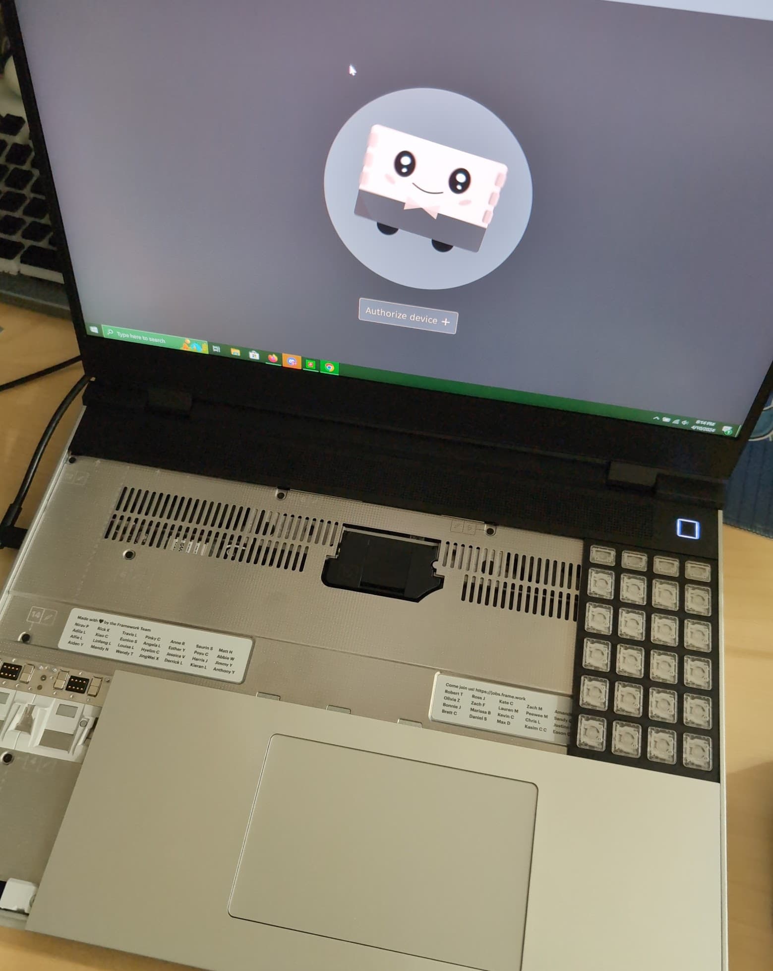
I forgot to add that it’s not possible to populate the input deck with only 2-width and 1-width wide input modules for the whole width of the laptop ![]()
Those middle connectors are meant for the touchpad, they’re i2c, not usb. So medium or small upper modules that try to use those middle touchpad connectors wouldn’t work anyway. You need a keyboard sized module to span the upper middle section.