Motherboard photos and dimensions

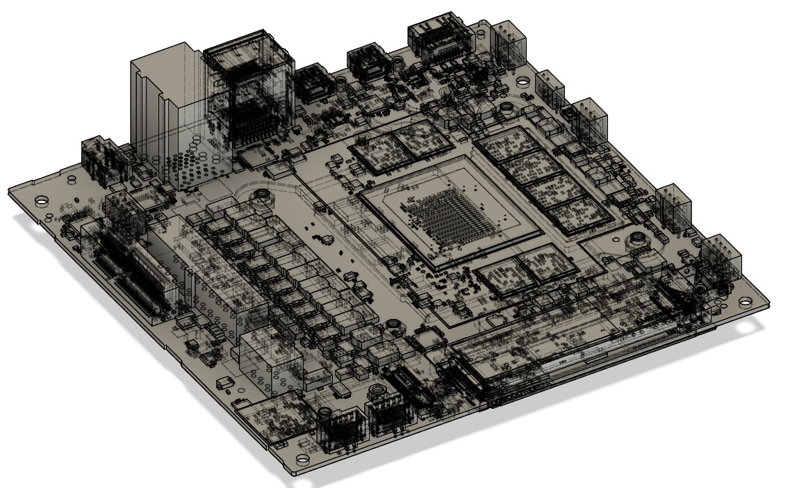
I’m starting on a build using the framework desktop (obviously). But I’ll be watercooling the system, as you probably know the cooler makes contact with not just the APU but also the RAM modules and the VRM, so I’ll be building a custom cooler/heatspreader/etc to cool those. But since I couldn’t find good pictures online of the naked motherboard, I took my own.

Photos taken at 4-ish feet away then zoomed in and cropped to minimize perspective issues.

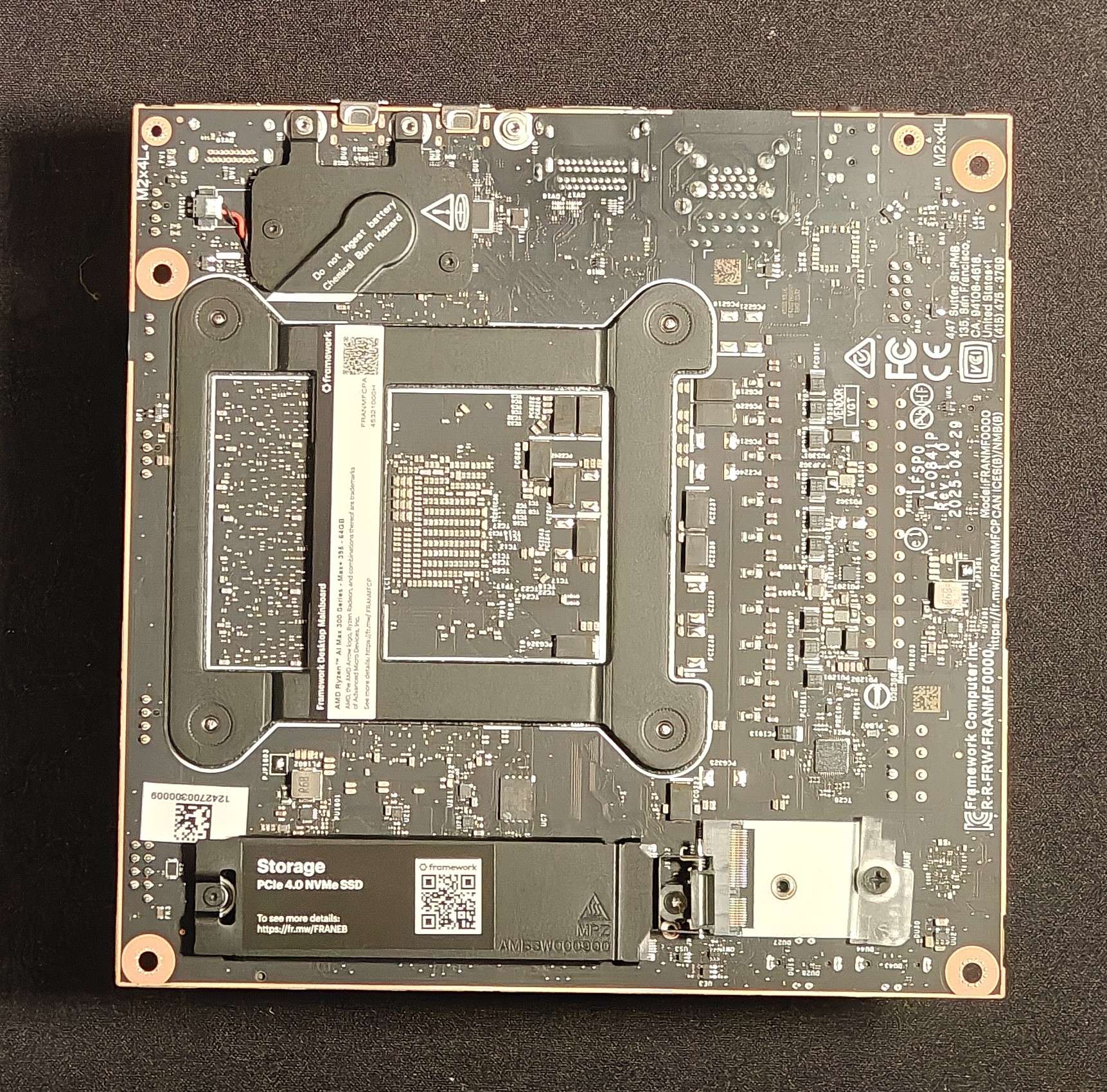
And one photo with both and a ruler for scale:

4 Likes

All the thermal pads seem to be 1.25 mm thick
edit: 1.25 might be cutting it a bit close, probably want 1.5mm pads with these measurements, see comment about heights of different chips below

Ram Modules: 15x12.5 mm
CPU module: 38x45 mm

If you wanted to cool the CPU and RAM you’d need a plate approximately: 89x59.5

If you wanted to cool the CPU, RAM, and VRM you’d need a plate approximately 107x 103 (103 could not be measured directly)

CPU contact on the cooler seems to be raised up 0.5mm from the plate that the RAM pads sit on

The RAM is raised up 2mm from the row of R15 chips that are cooled
(edit: I should clarify this, the R15 chips are TALLER than the ram on the motherboard, so on the cooler that area is recessed to have clearance)

The other VRM thermal pads are placed on a plate the same height as the plate the RAM pads are placed on.

Lastly, the cooler mounting holes are 78x87mm.

I haven’t double/triple checked my work yet, but figured I’d share what I have. I plan to make a rough model of the motherboard with all the required surfaces to then build my cooler off of. (the model on github doesn’t include the VRM chips at all)

4 Likes

Also fun fact, if you use a solid motherboard tray and 0.25 inch standoffs, the M.2 hinge on the underside of the motherboard will hit the motherboard tray and prevent you from screwing it down without bowing the board. Turns out that hinge is 0.28in tall…

1 Like

Any chance you could measure the distance from the top of the motherboard to the top of the CPU, please @Arkratos ? Thanks very much!

Do you mean how far it sticks out from the motherboard PCB or do you mean how far is it from the edge of the motherboard?

It is:
42mm from the “top” edge of the motherboard
67mm from the “front” edge of the motherboard
58mm from the “back” edge of the motherboard
90mm from the “bottom” edge of the motherboard
rounding to the nearest 1 mm (plus or minus 1 mm probably)

REALLY hard to measure, but I believe the CPU is 1.5mm tall…
rounding to the nearest 0.5 mm

Ram Modules appear to be 1mm tall (I’m not taking off the protective covering around the CPU and RAM)

R15 chips are 2.7mm ish tall…
the other VRM chips are about 0.9mm tall, which makes sense because the difference in height on the heatsink is about 2mm, thermal pads can soak up the difference in a few tenths of a mm.

speaking of thermal pads, I’m thinking the pads might actually be 1.5mm… it’s VERY hard to measure something that small that’s also really squishy even with calipers

Yes, protrudes upward from the PCB (metaphorically … as if its a skyscaper roof above the PCB roadway)

I think you’ve answered my question, tho … about 1.5mm … is that about right?

yes, basically I had to take a straight edge, lay it on the CPU and then measure above a clear spot near the CPU how high the straight edge is above the PCB… I got 1.5mm

results could be skewed if for some reason the CPU isn’t parallel to the PCB, but that’s what I could do to measure it

1 Like

As additional resource, there is a step file of the mainboard pn Framework’s github page. It has precise dimensions on APU and RAM but lacks any information on the VRM for whatever reason.

There is also clearance information in a PDF file there.

With heat transfer pads, make sure you get ones that are soft enough. I think mine where a bit too stiff for my mounting method and it was challenging to make good contact with the CPU dies because of that.

So in this pic… are the DDR5 identifying marks scraped off or painted over by Framework? Was curious who the manufacturer is but they look scuffed w/o writing.

I think that’s just the resolution of the photo, it was taken 4 feet away, zoomed in, and cropped… Pretty sure they have the markings on them… but I’ve fully put the cooler back on to test some d-gpu stuff and wont have it off again for a few weeks probably :frowning: sorry, maybe someone else can get the info for you?

No worries. I believe they use Micron memory, I was just wondering if I could confirm. (someone on the forum pointed out to me it’s possible new systems “may” start shipping with Samsung mem modules) Thanx.

This is a repost from here ………………..

“I’m missing something in reconciling the measurements of the heatsink, fan, and shroud and would appreciate some guidence.

Based on the image below I read that the heatsink alone extends 48.88mm from the top of the mainboard. Is that right?

image

233×614 4.93 KB

Based in the image below I read that the heatsink, fan, and shroud extend 83.2mm from the top of the mainboard … is that right?

image

282×601 6.68 KB

If I am correct and I deduct the heatsink from the heatsink, fan, and shoud (duct) the combined fan and shoud would be 34.32mm. Again, just checking that I’m on the right path at this point, or have I missed something?

My own measurements of the fan and shroud make their combination 32mm

I haven’t received my mainbaord yet (it’s seems to be on a foodie tour of South East Asia) so I’m wondering if there is something I am missing here?

Thank you”

  1. where did you get those technical drawings? (I guess I missed them on the official github :sweat_smile: )
  2. I took my fan off, which is a Noctua NF-F12. It has rubber bumpers on the corners that make it just over 26mm (even as much as 27mm if I’m gentle) thick when I measure it. If I put the shroud on, I get right about 35mm thick… but that’s without compressing it. The shroud has a thin foam layer where it makes contact with the fan. If I try not to compress it, it’s right around 8mm, if I compress it fully with my calipers I get 7.2mm.

So my guess is part of that is that foam layer giving you some play. 25mm fan + 7.2mm shroud = 32.2. If you have a fan with bumpers, which does appear to be the case in their drawing, it’s like another 1-2mm thick and if you don’t tighten it down super tight, you could easily get the 35mm that I measure uncompressed.

TLDR: the shroud is 7mm thick with a 1mm foam gasket that compresses to 0.2mm. And Noctua fans (which are in the drawing) tend to be thicker than 25mm because of the anti-vibration corner pieces.

Hope that helps!

It does, thank you!

I think its time I invest in a vernier caliper and some new glasses :glasses: :disguised_face:

I assume you found the drawings? If not, I linked them in my post above and again here

1 Like

Did you have the mainbaord only or the full Desktop with case? I’m curious the length of the non-thread part of the standoffs.

My standoffs are 5mm which is too short. The bottom SSD spreader looks to be about 5.5mm or maybe a bit more

I don’t have the desktop, just the main board. And yep the bottom heatspreader was longer than my standoffs too. Which ended up being fine because I put an M.2 → PCIE riser in that slot anyways…

Also heads up Framework updated the .stp file on github

2 Likes