Where were you a week ago? ![]() I should be getting the test print this evening to check fitment of the v2. Your measurements are more accurate than mine, but don’t seem too far off from what I had. If mine doesn’t fit, maybe Andrew will need to update his specs and we will have to retry. It is also very possible measurements are different board to board, which is why we started this in the first place. I’ll know more this evening.
I should be getting the test print this evening to check fitment of the v2. Your measurements are more accurate than mine, but don’t seem too far off from what I had. If mine doesn’t fit, maybe Andrew will need to update his specs and we will have to retry. It is also very possible measurements are different board to board, which is why we started this in the first place. I’ll know more this evening.
1 Like
No need to apologize! I knew we were working through a series of folks, so exporting an STL of the same model was by far the simplest option. Looking forward to seeing how well it fits for you!
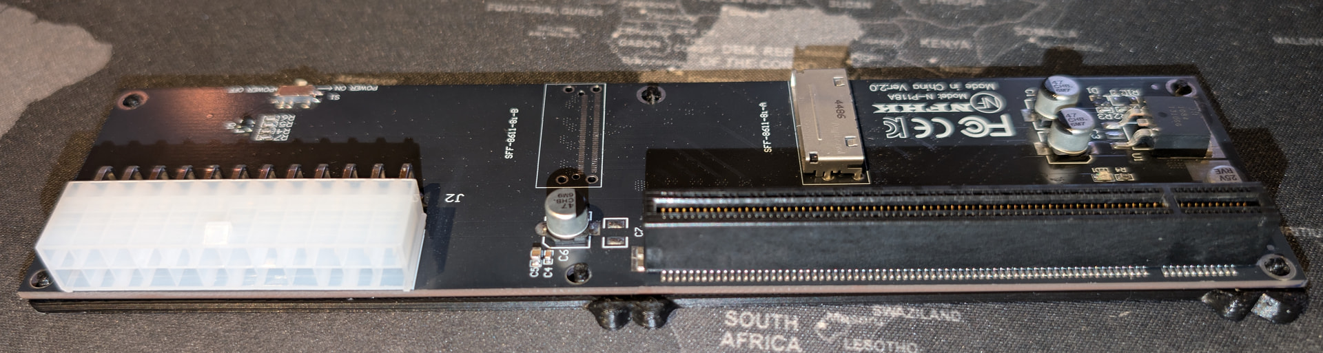
Should be around 200mm in length - if you’re able to print and test, it’d be great to compare your fitment to @OVER_CL0CK ‘s. As he noted, we’re checking for variance from the factory to see how wide tolerances need to be to accommodate the boards we’re getting.
Good to have switch placement too; if we’re trying to have it accessible (I think we would), we’ll need to know that.
Me personally, I don’t use the switch. Leave it in the on position at all times and just flip the switch of the psu each time ![]() it’s more easily accessible.
it’s more easily accessible.
1 Like
![]() had to finish stuff for work and not reading all the messages in this thread. I’m printing n-p118a-v20-alignment-test.stl right now (PLA/draft), I’ll post here photos after the print.
had to finish stuff for work and not reading all the messages in this thread. I’m printing n-p118a-v20-alignment-test.stl right now (PLA/draft), I’ll post here photos after the print.
for the switch, I think it’s not really needed, we should keep it always on or it will not work during the boot, or maybe there is another way to have dynamic poweron/poweroff like using thunderbolt adapter
1 Like
OK, printed and tested. It doesn’t fit properly into the holes, but only by a tiny bit. Printing again with resizing 101%, with lenght from 189.00 to 190.89 and distance between inserts from 102 to 103.02, and from 91 to 91.91).


Aw man, so dang close. My measurement must not have been accurate enough ![]() guess I’ll have to expect this when I test my print fitment this evening
guess I’ll have to expect this when I test my print fitment this evening
That’s why we’re doing the tests! ![]() I want to avoid folks needing to print much bigger, time and filament consuming models just to find things are off by a millimeter here or there. Plus - I’m curious if yours “fits” at first blush or not.
I want to avoid folks needing to print much bigger, time and filament consuming models just to find things are off by a millimeter here or there. Plus - I’m curious if yours “fits” at first blush or not.
@polxmod , thanks for the dimensional change notes! I’ll update the model when I have a few minutes today and pass it back for you to take another crack at when you have time.
It’s also helpful to know if two pegs do fit, and a third doesn’t, for example - that tells me where the spacing is off (is it scale, or is it specific between pegs, and so on).
sure no problem ![]() better to print 8g than 100g.
better to print 8g than 100g.
tested the other print with small change in scaling (101% longer). now it fits but the inserts are not centered in the hole.


1 Like
I can confirm this results from my test print (100% scale). I printed 2 with different filaments, the first with PETG and because the quality of the print was really shitty (I don’t know why I struggle with PETG so much) the second one in PLA. The PETG looked almost the same like yours (but in much worse print quality ![]() ). The PLA one (→ the picture) almost fits, but is very tight and therefore minimal bent.
). The PLA one (→ the picture) almost fits, but is very tight and therefore minimal bent.
Because of the differences between the prints, I wanted to wait for other results.
It’s also helpful to know if two pegs do fit, and a third doesn’t, for example - that tells me where the spacing is off (is it scale, or is it specific between pegs, and so on).
In my case it seems the outer ones on the PCIe socket side are a little bit missplaced to the center. If I put the board only in the center and the power socket side, it looks good in my point of view.
Nice, thanks for giving this a shot! I’m in the same boat, seems like PETG needs a lot of coaxing to come out well on my printers.
I’d recommend printing with PLA for dimensional accuracy right now - it’s cheaper and tends to be easier, plus it avoids potential shrinkage from PETG filaments. Ultimately I’ll try to release actual dock mount/case models for printing with PETG and ASA filaments that can accommodate expected shrinkage. (Another option is having folks print a test like this jig to test their printer and filament’s specific shrinkage and calibrate their case/mount prints accordingly… we’ll see what’s needed when we get that far. ![]() )
)
@polxmod , I’ve uploaded a new .stl and .3mf using your dimensions - the measurements do seem to align with the scaling you found worked better, so I’m crossing my fingers these might just be it. ![]()
Is your filament calibrated for shrinkage? The margin its off looks like the shrinkage factor.
OVER_CLOCK’s measurements were done by ruler, and polxmod’s measurements were slightly more precise (taken by caliper) - so I’d say we see how today’s model does based on the caliper measurements before we dive into filaments. I’m hopeful we’re very close now.
1 Like
I quick started up the 3D printer and printed the version “N-P118A v2.0 Alignment Test 2026-03-06” with PLA. It now fits very well with my board.


Lets hope, polxmod can confirm it ![]()
1 Like
Hey.. you recommended the ruler from the start![]() I do not have a caliper.
I do not have a caliper.
2 Likes
We do what we can with what we have! To be honest, getting within a half a millimeter of accuracy with a ruler is pretty dang impressive! ![]()
2 Likes
I’ve tested the latest version and it fits like a glove.
if we are ok with the measurements I can test it with PETG.


2 Likes
Well it appears that a few people now have tested fitment for the v2 board which after slight modifications, it seems to fit well. Likely can conclude the boards are the same measurements. Unfortunately I still wasn’t provided my test print to check mine yet ![]() but I am willing to bet what you guys have been verifying is going to be the same for mine too.
but I am willing to bet what you guys have been verifying is going to be the same for mine too.
Tested PETG-HF as well. It’s performing just like PLA. no warping or shrinkage, so the measurements are confirmed correct.


2 Likes
Hey guys, absolutely amazing! I am still wondering, could we use this prototype as a basis for a full EGPU enclosure? So it would be an adaptation of the ones below. And I know this is wild, but I was wondering to even allow for two noctua fans at the top for airflow (you could choose the ones with very low noise levels (redux), and just attach them via a cable directly to the PSU, then running at 100%). In addition, I would suggest space for a 4 slot GPU. Unfortunately, I do not have practice in 3D printing design. But I wanted to ask if someone would be interested, otherwise I would go to a 3D printing lab and ask them.
My only issue with this is that the OCuLink 8i cable goes in the opposite direction of HDMI and power cable for GPU and PSU. This will make it look a bit weird as the OCuLink cable will probably have to stick out as it would be attached all the time.