Hey there FW Community! Just wanted to put it out there that I was a little late to the party to join this forum (though I have owned my FW16 as of batch 17) to learn about the LM issues not adequately keeping the CPU temps down, causing throttling and drastic differences amongst the cores (up to ~20 degrees from coolest to hottest!). Long story short, I have just been tinkering (as most of us are surely doing) teaching myself new things and reading up where I could. I have already performed several tests and documented and submitted the data through a support ticket over several days to which they found sufficient enough evidence that I too suffer from this problem. That being said, I have done a ton of reading from other users and just wanted to get tips and tricks that you personally found helpful during the swap to hopefully make the process as seamless and efficient as possible.
Some simple tips I have heard about:
-Run a stress test to heat up the CPU. Power down and flip over for LM to cool mostly on the heatsink instead of the chip for easier (hopefully) removal
-Use 90% isopropyl alcohol for finer removal
-Paper towels come in handy for covering other components during removal
-The back of the FW screwdriver works well for not only clearing remaining LM but also to seperate the heatsink with careful pry from the board/die
-Place PTM in freezer for ~5 mins before handling before applying to help prevent tearing
A question I have:
Should I be applying this PTM directly to the die? (Removal of the original LM tape & foam barrier) What I have been reading seems to indicate that this acts very similar to thermal paste (though it does turn from solid to liquid and should indeed be applied directly to the die; but oddly enough I have seen many users place it on the original barrier where the LM originally was and the barrier remain between the PTM and the die. What is your experience?
I have the PTM on the way and should arrive 7/28 and want to prep accordingly, but will be out of town this weekend. Please just share some of your insight and much appreciated!
Also, before we go off the deep end I will clarify that I am in no position to be going the extra mile like some users that completely removed shim on heatsink and filed the heatsink down, replacing original shim with a copper shim PTM “sandwich”. I just want to as best I can with what I already have.
Thank you in advance for all your advice and support! Stay helpful out there
I am confused with people describing the original solution as “LM”. I understood that this was also a phase change material which was liquid while hot and solid when cool. There are numerous posts describing how owners were removing it in it’s solid form.
Correct, still a phase changing material and “LM” is just an abbreviation for liquid metal. I simply put up this post to see if there was any other tips/tricks folks would be kind enough to provide that I may have missed.
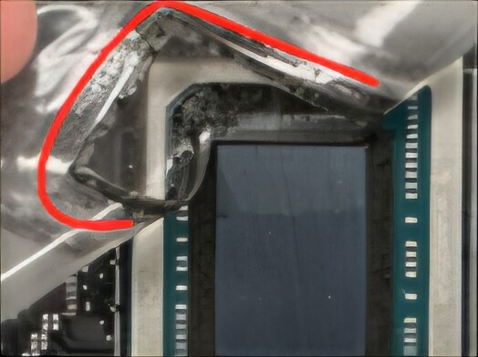
There is nothing else to apply it to. The foam barrier is not between the die and the heatsink, but around the die. The foam barriers glue is quite sensitive to alcohol, so if you’re using that to clean the die, you’ll not have a foam barrier anymore.
For some reason my other post in response to you is still pending mod approval. Idk why.. in any case don’t be surprised if that shows up after. But I think I finally found a better image to clear this question up for myself. It is indeed not covering the die, but around it. In learning this, I am likely going to try my best to keep the original shield intact.
I think you might have answered what I was looking for. I’m aware the foam barrier is around the die. What I was confused about (since I’ve yet to actually crack it open until my order actually arrives) is the white protective layer to prevent spillage on the mainboard. Are you saying it is an empty space where the LM sits so it has direct contact with the die? It almost looked like there was a layer that went all the way across and stuck to the die on one video I saw when they completely peeled it off. Link just for reference on shield I’m referring to.
There should be no barrier between die and cooler. (Step 02 and 21)
The general use of the LM/PTM/… is to maximize the contact between die and cooler.
Any layer of material between die and cooler reduces the thermal conductivity. (Especially sponges since they are very porous). The only reason to apply LM/PTM/Thermal paste is to fill tiny gaps in between.
Just some background info on LM. Different manufacturers have different blends of metals to make LM. Some manufacturers will have more gallium than others, that aids in how “liquid” it is.
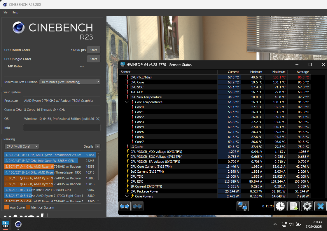
Well folks.. the swap has been completed and I must say.. performance is phenomenal. Very pleased with Honeywell’s product. This is both the second boot & test I have done since and here are the results. I think case closed.
Edit: Snapped that right as test finished and cpu was still coming down (hence the still high current temps). In addition, this is on performance setting (power plan), not over clocked and with a -20 curve undervolt..