makes sense, i think usb as a whole is a pretty durable interface
id imagine that its mostly an issue when optimizing speed for drives or when you have the 3.3 superspeed
definetely for thunderbolt because it exposes pcie, etc
makes sense, i think usb as a whole is a pretty durable interface
id imagine that its mostly an issue when optimizing speed for drives or when you have the 3.3 superspeed
definetely for thunderbolt because it exposes pcie, etc
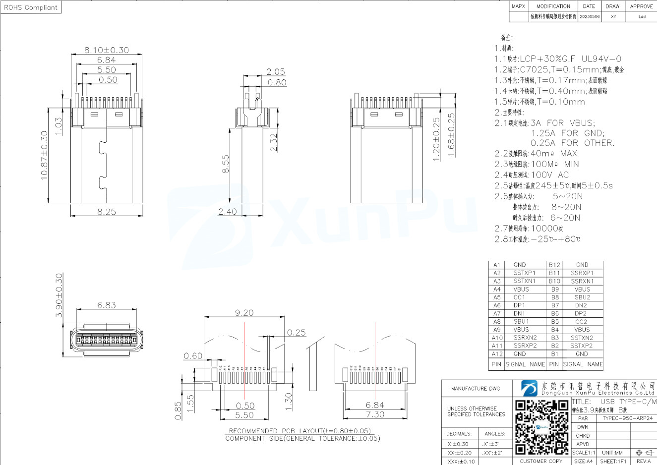
I consulted NextPCB engineers directly on which male type-c configuration they would be happy with. They told me that TYPEC-950-ARP24 is easier to mount with more clearance that their machines are capable of achieving. I will modify the base expansion design accordingly and share it for all to use, so people can get expansion cards produced with simpler machines.
I have revised the expansion card template to accomodate TYPEC-950-ARP24 connector. Here is the 0.2 clearance/0.4 panel V-CUT friendly version:
Ye gods I hope this works as expected ![]() I’ve got one of these: Pimoroni Tiny 2350 and tried rigging a male-male usb-c cable and it’s just slightly too big to fit into an expansion case.
I’ve got one of these: Pimoroni Tiny 2350 and tried rigging a male-male usb-c cable and it’s just slightly too big to fit into an expansion case.
My particular usecase is to put a tac switches on the case so when I press them they do things like lock screen rotation ![]()
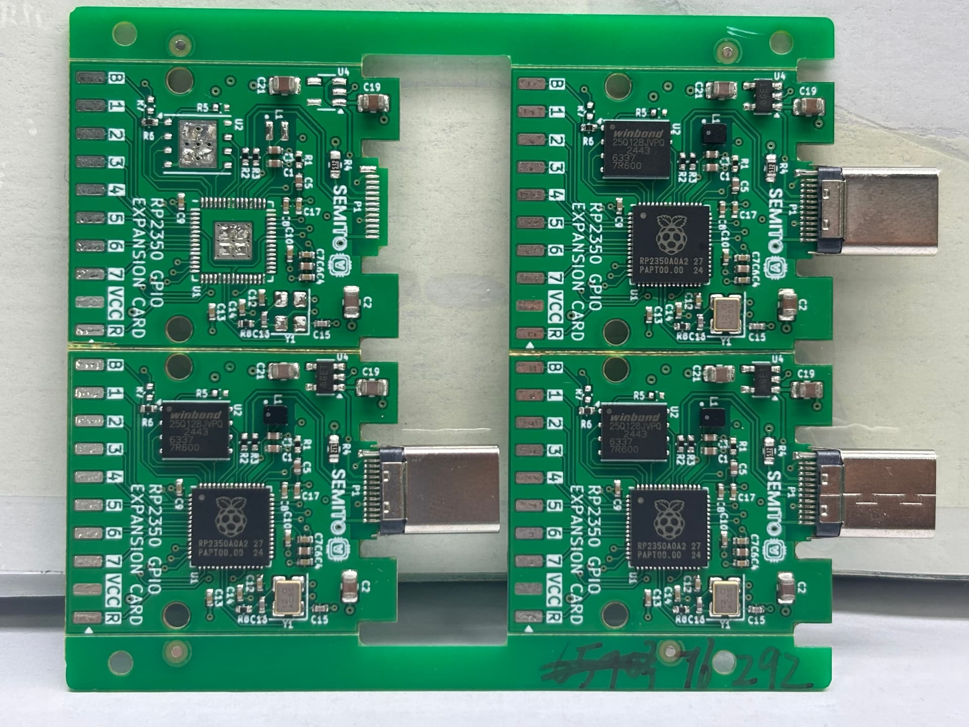
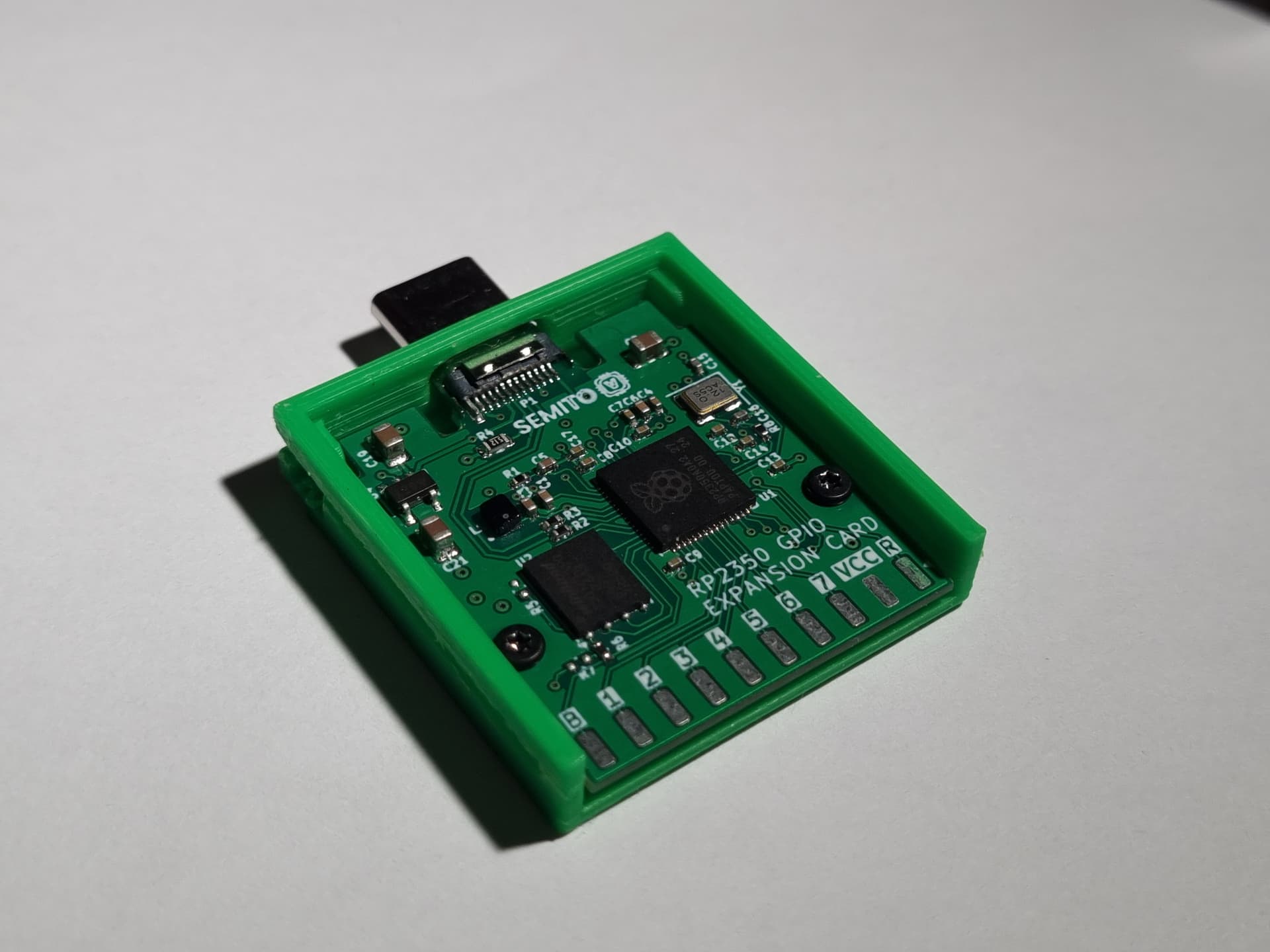
Is it just me or does the left usb-c connector look crooked?
Oh its just that they haven’t soldered the back side of it yet. This was actually a one side PCBA order to reduce costs but TYPE-C of course require double side so they will just solder it with no additional costs.
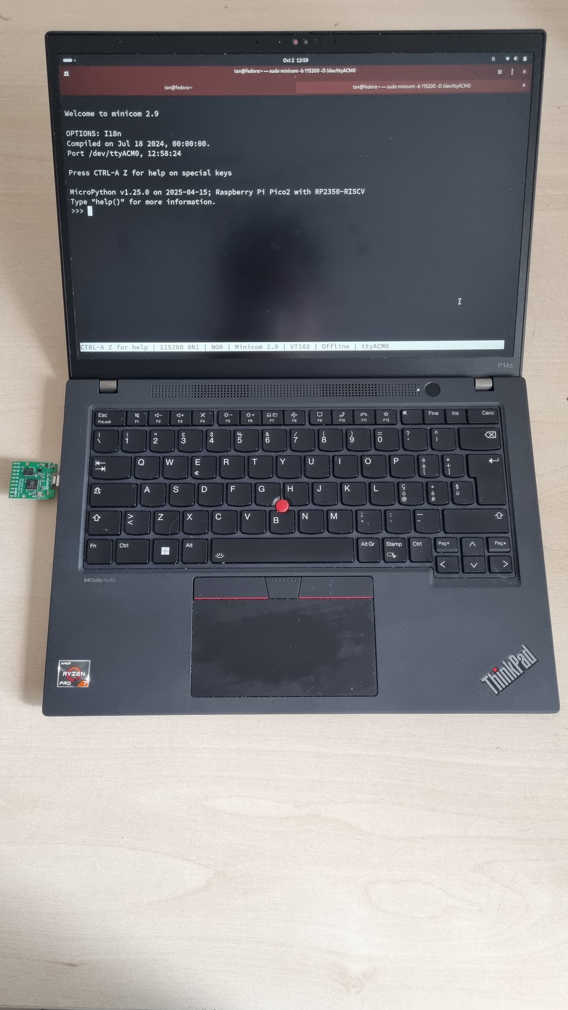
I just received them today, and MY DESIGN WORKS! I can’t find words to describe my joy! It just works! (Doesn’t work with DC-ROMA RISC-V Mainboard yet which is only Framework pc I have due to cdc_acm module missing in the kernel. We are working on it with DeepComputing team.)
I just soldered male headers and all pins seem to work! I will test ADC and SPI/UART/I2C soon.
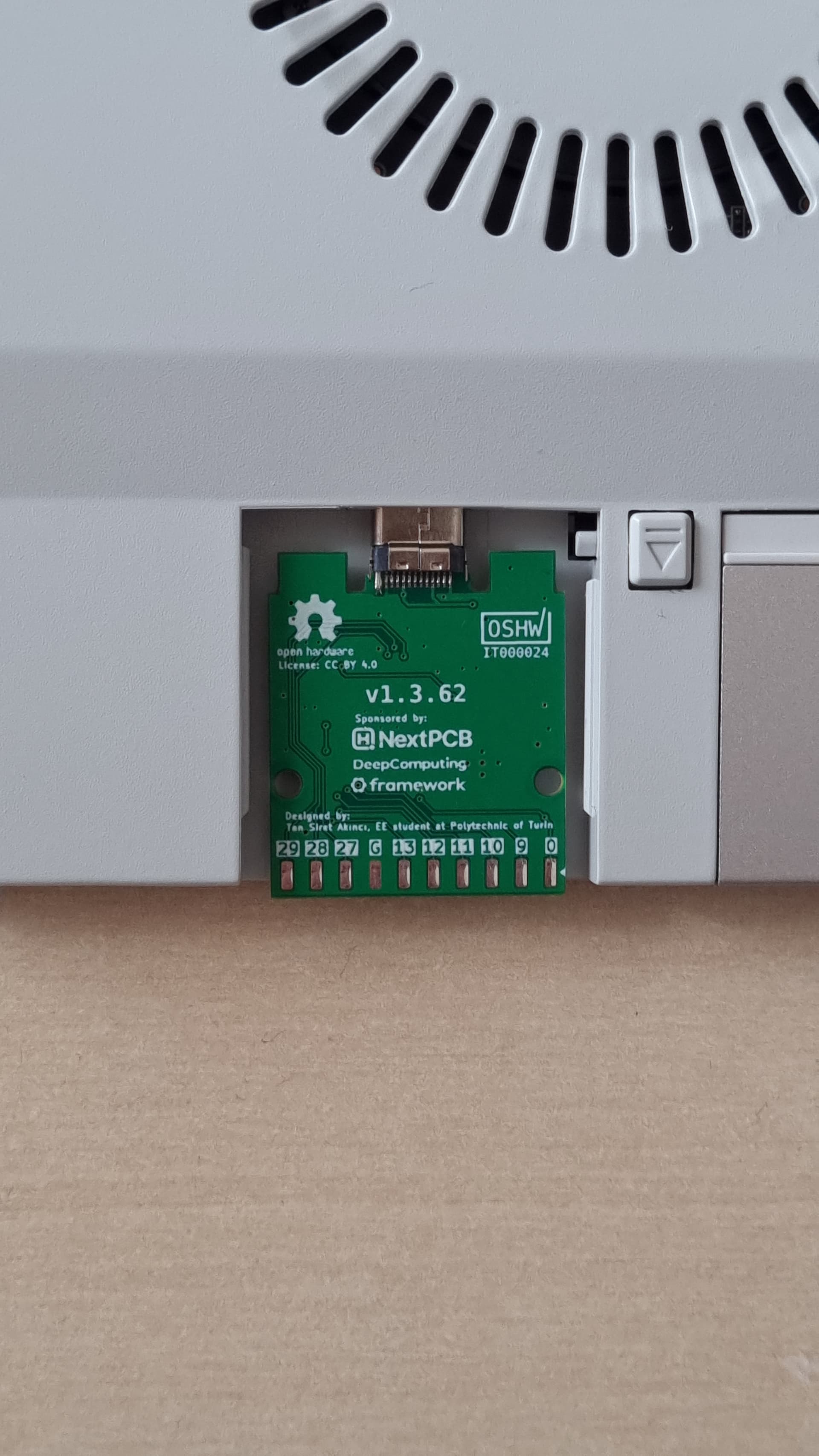
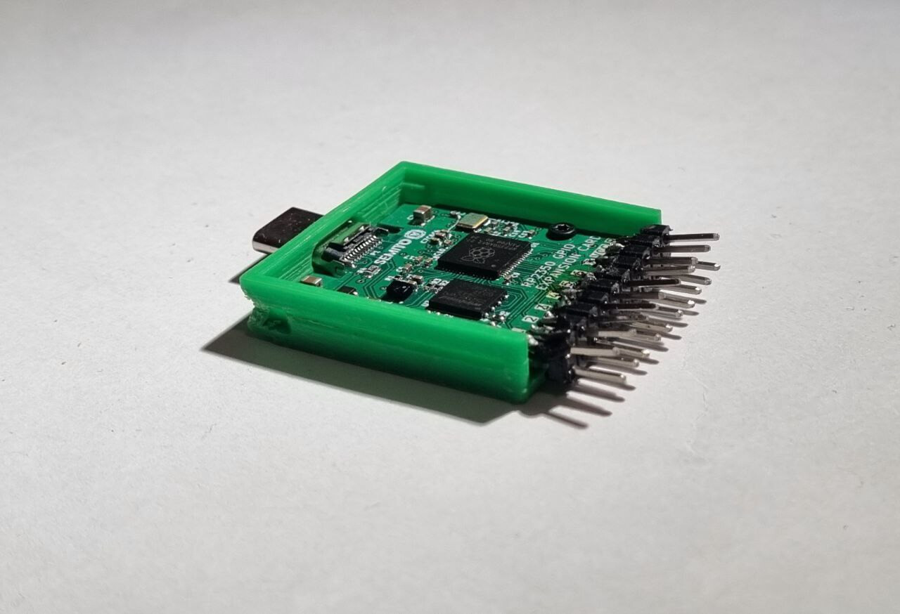
We have conducted tests with DC-ROMA RISC-V Mainboard and it works after unminimizing the distro and recompiling the custom Linux kernel with cdc_acm included as module! Legendary @XenoCow known for his snack drawer designed us a 3d case that just fits perfectly. Thank you Xeno! I love this community and open hardware community in general!
Possibly the most RISC-V cores to ever be in one laptop?
For now that seems to be the case sir… until I possibly design another expansion card with multi core RV64 based SOPGHO SoCs or FPGA running our own cores.
Or plug in four, one in each bay! That’d give you 16 RISC-V cores ![]()
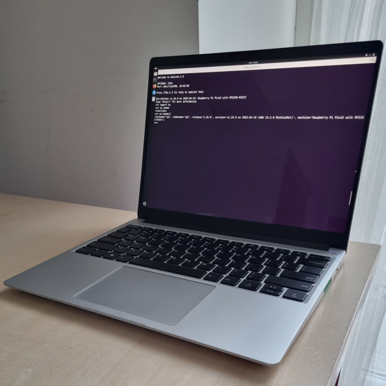
Pals in SemiTO-V Software Task Force have developed a library named “MCL” (Micropython Compatibility Layer) that allows you to write Micropython code targeting MCUs inside PC Python (CPython), as if the PC itself has GPIO!
I LOVE Framework and whole open hardware movement!
Following is a demo with the card connected to Framework Laptop 13 with DC-ROMA RISC-V Mainboard I by DeepComputing inside:

Very neat! I’ll have to test this out later…
It might be useful to add a description about how this is different than running something like Thonny directly, and interacting with the module that way.
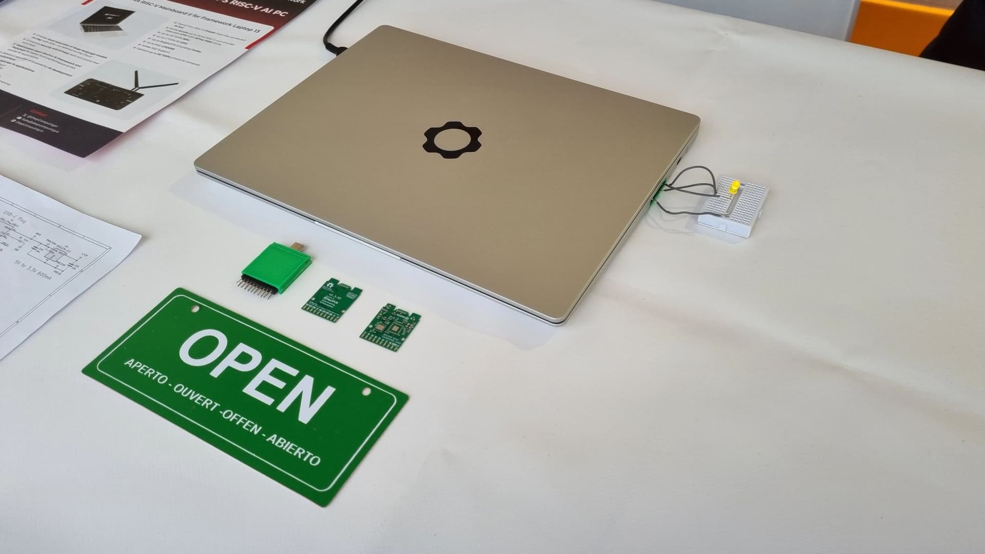
Visitors in Maker Faire Rome 2025 liked the card! There were a considerable amount of Framework and RISC-V enthusiasts, but most of the folks learned about both at our booth. Here are some photos:
Note: All photos are CC BY-SA 4.0 so feel free to use them!
This looks amazing! I can see myself using this quite a bit. Do you know if/when the PCB will be available for purchase?
Hey, thank you! Unfortunately I can’t sell it due to it being a student team project. But I may make a similar expansion card myself under a brand and sell it in the near future. I will let y’all know. ![]()
awwww, I will definitly be interested that expansion card if/when it releases
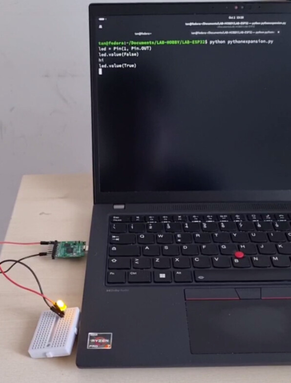
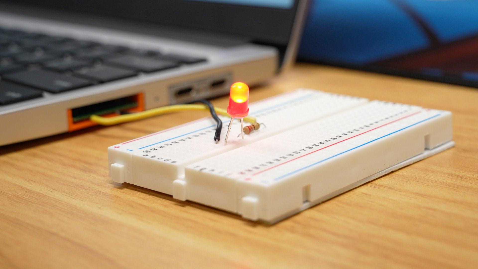
Oops, I posted a message in the wrong thread (too many tabs open today lol), but I got mine to light the LED using the led.py example:
What kind of headers are recommended for easier plug/unplug using header pins? Just a 2x10 pin header, with the legs folded down towards the PCB?
Right now I just have leads soldered to GND and GPIO 10.
Hi Jeff, I soldered 2x10 header myself but to my ignorance its loose as the PCB is 0.8mm, not thick enough like other boards where its implemented. So its kind of a botched job where I bent the headers with soldering iron which kinda melted the plastic for that to happen:
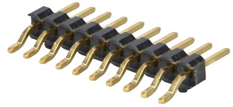
That being said you can get 2 angled 1x10 pin headers on each side, like “10-pin SMD pin header, angled, pitch 2.54” below, which shouldn’t have any issue: