Hey there,
my name is Nico Maas and I am working for the German Aerospace Center (DLR). While keeping the lights (and IT) on in our controlrooms (for ISS and other experiments) is cool, my real passion is developing experiments for sounding rockets. Small rockets which venture into space for a small amount of time and bring back the experiments via heatshield and parachute. While the micro gravity times are not as long as with more “permanent” platforms (like satellites, space stations, etc) - the six minutes we achieve are more than long enough to gain significant scientific insights. To this day I had the honor of designing, building and flying 3 experiments to space - with the last one supporting cancer research. While (due to the funding issues) most of my experiments are build by myself in my sparetime and only certain components are paid for by my employee (and the project is too important to shelf ) - I was very happy to see Framework announce their Creators program - giving away a Framework Laptop motherboard to people which had an idea how to use it. I applied for one and luckily got chosen.
What I want to do with mine is relatively simple: While the experiments are within the rocket, they need to be provided with power, signals (have we left the launchpad? Have we reached space? Are we due for re-entry?) as well as a telemetry pathway (signals and sensor data from the experiment), a telecommand pathway (the possibilty for the experiment to get commands on what to do next, start different cycles, etc) and a video channel (i am providing a video signal from a flying microscope my colleagues of the flight medicine built afterall. we want to see what our samples are doing! ). All these requirements are satisfied by a drum called “Service Module”. And as the experiment is built against the requirements and interfaces of this system, it is more than important to have one for yourself. Ok. Those things are downright too expensive - so that not many exist on earth. That means we have to do the next best thing: Simulate it. And as we all know: Simulation needs a lot of processing power.
While the interface to the experiment is handled by (the now third generation of ) a simulator box I am building, there needs to be some control. The framework motherboard has more than enough power to run the complete environment consisting of Mission Control Software for the Payload, Timeline Simulators, Countdown Clock Simulators and Video Recording - as well as giving a Touchscreen to give basic control over the system.
While I will not be able to cover everything in greatest of detail - due to the nature of the project (and some papers still being pending regarding parts that will be used in this project), I will still like to share some progress
And this is what it could look like in the future:
First entry:
I got my motherboard on Thursday, 30.06. and directly put my Micron DDR4 Kit in it, added my 60 Watt charger (because the original Framework Laptop also got one, so I bought this) and powered on the device. Well, that did not work. I only got blinking error codes. I looked through the net and found some explanation that told me the power was ok, RAM also, but the CPU had not started - and the FAN was not spinning - which was what I could observe. I tried further, landed on this forum and opened a topic the same night: Framework Motherboard does not power on / blink code
Luckily, @Azure and @Xavier_Jiang were so friendly to inform me, that my power supply was insufficient. Trying to use the motherboard without a battery would need a 100 Watt power supply, with battery only a 60 Watt. While I found that a bit concerning, I found enough evidence in the forum that I though I might give it a try. I bought a Spigen 120W GaN Fast 4-Port Charger and an Spigen DuraSync USB C 100W 1m cable - to be sure that would work. The supplies arrived on Saturday, 02.07. - and it did not change the situation.
I got in touch with the Framework Support Mail and those nice guys talked me through everything: Reseting the RTC Clock, getting a Video of my Postcode, “Hot Swapping RAM” in hopes to get it working. In the end they remarked that my memory (while being one kit of Micron and one of Samsung RAM) was not on their compability list and might not work / could be the issue. I was a bit reluctaned to go on there: The POST code said voltage was ok, RAM was ok. The CPU was not booting at all - I had removed all other devices (like NVMe) to be sure nothing could hinder the device - it was just power via the 120 Watt brick, a short 1m/100 Watt rated cable and the memory modules. I also let the RTC battery charge since saturday, but no joy.
In the end I bit the bullet, tried to get in touch with @Bee (who is leading the Creators program) - remarking that I might have a “dead on arrival” motherboard - but did not an answer yet. I did buy one stick of Kingston KVR32S22S8/16 RAM the same night - which arrived today. Sadly - as I feared - the board is still dead.
Now 17 mails in with the support I hope they send me a replacement board, because there is nothing more on it that I could change on it.
(Thanks at all the nice people supporting me so far )
This is a very cool project! While it’s unfortunate that your first mainboard was a lemon, I wish you the best in getting a replacement, and I can’t wait to see the progress you continue to make!
Note that the Mainboard can be powered using the 60W Framework Power Adapter (or other similar wattage USB-PD adapters), as long as the firmware is 3.07 or newer, which all new Mainboards shipping out now should be. The DOA is definitely unfortunate though, and we will certainly swap it for a functioning one.
Thank you @Azure - yeah even with the best QA/QC sometimes something slips, that just happens. However, Framework has proven to have an awesome support and while its unfortunate - its a good show of their commitment towards the product and their customers. They already got in touch with me and got my address to send a new one out and am very excited to get this project on the way
@nrp Thank you very much for clearing that up, that is a good and solid information and I am happy that your colleagues got already in touch with me to send a new one, thank your for your support :)!
I just got the replacement board and it works like a treat - directly powered on, no issues, 3.0.7 firmware and its even working with my original 60 Watt power supply and cable as well as with my original RAM. It seems to be a bit picky about using UEFI boot from USB sticks flashed with the latest Ventoy (as not working for me with both SanDisk as well as Corsair USB 3.0 USB sticks) - but I also have not yet tried the newer beta release BIOS .
Very glad that it now works, thanks a lot for your help dear Framework Team !
Oh ok that was great. they did address this issue with the newer bios.
If only you can flash the bios externally … nah, can’t be bothered with an entire kit of ICSP programmer and clips.
Oh, I would be so into this kind of hack. Actually I got a clip for SOIC-8 chips (used them for programming ATTiny 85), but this would not find and I did not yet get an ICSP programmer (but might be able to bit bang something out of some of the dev boards I got laying around here). Sadly I had to return the defunct board and with that I cannot say if this really was just an old bios or other issue. The board arrived yesterday at their location (UPS tracking). However, I am really glad to be able to make progress now
why don’t you buy a battery, then “hack” it to take external power and have it report infinite juice so you don’t need a charger?
It couldn’t be that difficult. You could probably get a (extremely cheap) microcontroller to pretend it’s the battery IC and report all the metrics. Figuring out the comm protocol (e.g. the data request etc) is the more costly part.
Worst case you end up with 4 quality li-po cells to be repurposed
Not identical to a charger solution, tho.
So, after I got the working board I get some generic USB C “all in one” no name breakouts / docks to get the signals out. I am brain storming on all the parts I need, which means a lot of time consuming browsing on the “usual suspects” in regards of websites. Currently I bought a lot of nice momentary push buttons and a big emergency cut off (this will not be in line for the motherboard, just for the power going to be feed to the payload ).
Also I was thinking about the kind of water tight case I want to build everything into and might have identified a possible case - however, this one will come last. I frist want to get all other parts, losely assemble and see if I can squeeze anything into the needed space. Yeah, space will be a premium and people with more lu… tim… experience in CAD might draw this all beforehand… I have a more… practical approach to those things :D.
Regarding of seeing things: Monitor. Important. Should be high resolution. I actually wanted a touch screen, but might choose other possibilities. The guides here in forum ( Unofficial Guide to Aftermarket LCD Replacement , HDMI controller board for display panel , Matte screen please! :) ) hyped me up to get the panel and go that route - so I will see if I ever come to adding a generic touch panel with 13.5 inch above it - but @nrp@John_Perez and @Matt_Harris have already been incredible helpful with documenting their works, so its just awesome to tap into all these resources - thanks a million guys!
funny story, I actually (also) powered the first board via the battery connector from a bench power supply to see whether this would work (using the correct voltage range of the battery etc). And I also saw some current flow of up to 1 A. However, as you correctly state, most of the batteries have some sort (I think its talking via I2C) controller to report the state - and make the motherboard not charge or consume power if something is off (… like no controller there, answering or the controller blown to pieces… - and thats a highly valued security element, we don’t want to throw another Samsung-Note-Burning-On-An-Airplane-Party here…). So while it was drawing some current, it quickly ceased and the board never powered up. Would have needed - as you said - to reverse engineer the battery circuit for that and the protocol to be able to fake it. But it would be much more useful to get a real framework battery before, some spare battery connectors (male and female, to build myself a “sniffer”) and then attach a logic analyser. If I had the battery and needed connectors I might take a swing at it, but I have not.
But yes, this would also be the required pre-work to give the Framework Laptop a second voltage feed / UPS option and the possibility of adding own, big block battery banks to the laptop.
Successfully hacking the battery to allow a larger battery to be used is something I’m going to need to get working for my Ruggedized Framework
If anyone has any info on how to do it that would be great, not looking forward to trying to reverse engineer it, since ensuring you’ve got everything perfect so that it will be robust is really difficult if just sniffing the signals.
@Zachariah_Mears to be able to fit a new battery / bigger battery pack to the system you will have to understand the protocol and working perfectly. Reason is, a bigger battery pack will need more cells, so you will need to have different kinds of balancer and other circuitry. And Framework motherboard does completely rely on correct information from the chip within the battery, otherwise you run the risk of overcharging the battery or running it too low, which are both suboptimal states for LiI-Ion / could result into a really dangerous situation. So my personal opinion is, that there is no way around it, if you really want to use the battery port for that. Also you will need to find out how much charge current the motherboard can deliever, so that you don’t end up with a battery that big that you won’t be able to charge it in reasonable time (or provide external charging capabilities to the battery).
However, Framework gives you much headroom, I think I read somewhere that you can attach multiple power sources to the USB-C and the Motherboard will use the strongest one (needs to be checked again :)). If this were the case, it would be interesting to see wheter you can hotswap from one power supply to another. Meaning you could also swap from one USB-C battery bank to another (which you could built yourself with some normal available balancer circuits and its own Battery Management Unit, which are available from the shelf). Drawback would be that you would need to attach it via USB-C (if you don’t hack the motherboard with another power in) - and you would need to charge it externally. But capacity wise you could go wherever you want, you could choose your cell layout and chemistry as you would please and hence also have all possibilities of fast charging etc - without any risks. So this would be something I would lean towards
I’ll try and discuss it more in my own topic, sorry for derailing yours. but we’d forgotten that all the embedded controller firmware is open source a brief look found a lot of the battery parameters and it looks like the SMBus, and the Smart Battery System standards are publicly available, so we might go ahead with building our own battery pack that works with the built in connector as it looks very feasible.
I believe the current battery is a 3-cell. Or a 4-cell.
You can simply rip out the original small cells and replace them with Big Chungus ones and wire them back in.
You CAN link cells parallel to provide more capacity, HOWEVER I extremely strongly recommend not to do so. There can be stray currents between the two batteries which can lead to dangerous situations.
Internal battery cells do not contain protection circuit and are highly explosive.
Do not overcharge, overdischarge, overcurrent, short circuit, over temp, puncture, deform or reverse polarity. Proceed with extra caution and always isolate battery leads until ready to connect.
Even though I personally had a few sparks when working around with batteries and seem to get away fine. Always assume that any short/sparking will cause the battery to explode. Observe suspecious batteries in a dry area for at least 30 minute.
So re-use the battery balancing/management board that Framework come with. It might freak out because the capacity is much greater than the capacity set by the factory, but I believe it should be able to figure it out, since it gauges with the battery voltage.
So, I finally figured out a way to update the BIOS without having a battery (and documented it in my guide: Getting started guide with a bare motherboard) - so I have been updating from 3.07 to 3.10 and happy with that .
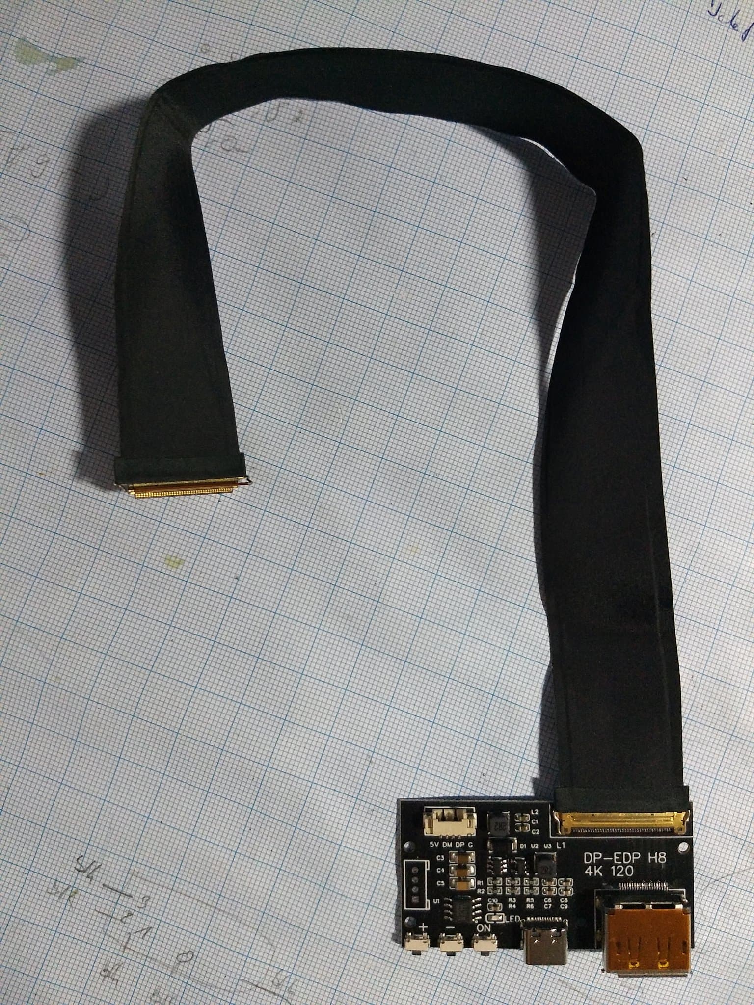
I finally also got my panel and controller ( thanks to the HDMI controller board for display panel thread ) and wanted to build the very fragile panel into a more rigid form.
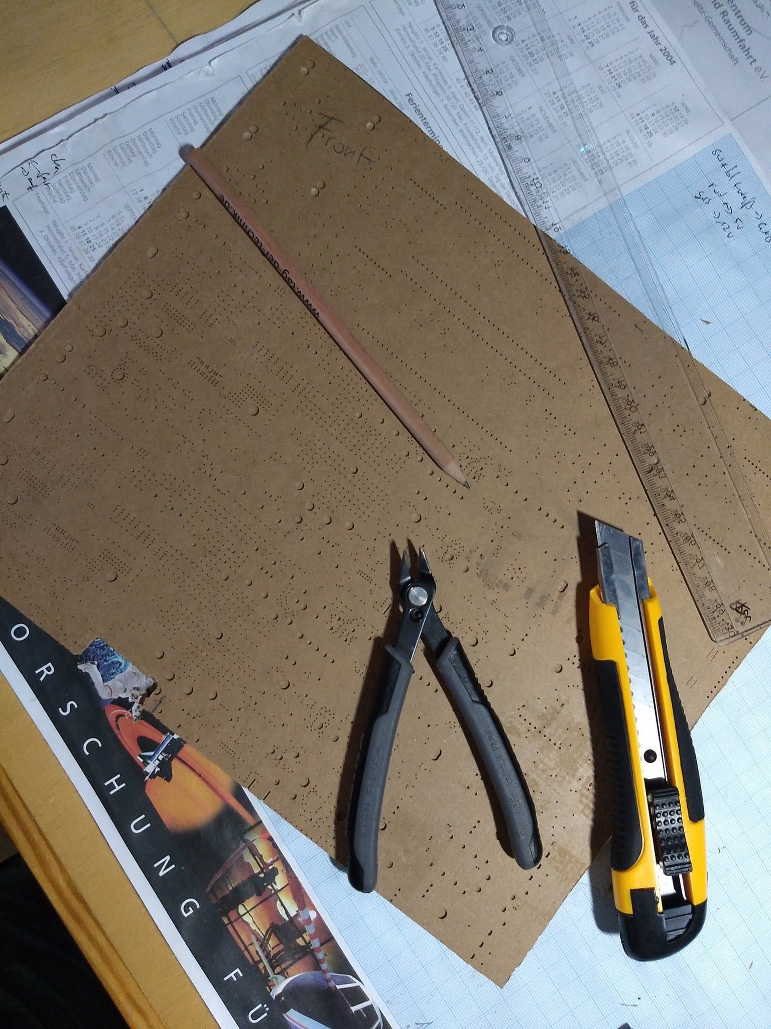
I started by getting out an old piece of “wood” (it is some protective material used for transporting PCB stencils - basically scrap, so I decided to use it, as it is lightweight and still reasonable solid for a first try). I marked down the outlines, cut out the display connector area and started gluing down everything with tape for a quick test
Next day, I thought “what about 3D printing some clamps?”. The panel is about 2.2 mm thick and has a “clearance” of about 2.5+ mm (the area from the edge of the panel until the screen really starts / picture is shown / the area you don’t want to be hidden by some mechanism). So designed 4 clamps, which can be printed upside down with support and 30% infill and can be fixed down with M3 screws (the hole is tighter, so that you can decide yourself if you will widden it with a drillbit and use some counter screw or just screw into the material - which will not be good for longterm use, but its an option) - I attach the STL at the end
Attaching the controller a bit hidden so that the displayport connector will still fit on the backside / does not stick out. And yeah, I could shorten the screws …
some of those switches are just like, so satisfying.
make you want to build a box just to have them so you can just click them around.
I salvaged a few C&K rocker switches the other day. Those are fantastic as well.
I finally got further with the project. I currently built nearly all necessary hardware into a water tight case, including power supplies and support equipment. The case has a top and bottom plate made out of 2 mm thick aluminium. The top plate holds the display, controller and motherboard (which is mounted on the basic 3D tray available from Frameworks Github repo).
To control the motherboard / allow for power on from the main control panel, I soldered two wires to the foil switch. I also an additional switch mounted on the bottom panel and can switch on / off the motherboard without needing to reach into the case.
Also I wanted to be able to switch on / off the screen independently, so I added the needed wiring to the controller boards “OK” button and extended it with another microswitch which I can now reach in built-in configuration. Very handy if the overall board is used in headless mode.
It would have been really useful if there were any replacement monitor cabling available to directly attach the display to the motherboard without the need for an external controller, but maybe Framework is fixing this some when - replacements for such fragile cables should be always available, especially if they have custom pinouts (which they have) and will help to give Framework laptops better repair-ability
 ) - I was very happy to see Framework announce their Creators program - giving away a Framework Laptop motherboard to people which had an idea how to use it. I applied for one and luckily got chosen.
 ). All these requirements are satisfied by a drum called “Service Module”. And as the experiment is built against the requirements and interfaces of this system, it is more than important to have one for yourself. Ok. Those things are downright too expensive - so that not many exist on earth. That means we have to do the next best thing: Simulate it. And as we all know: Simulation needs a lot of processing power.