I"‘d like to setup my FW12 vertically next to my main monitor when working at home. Ideally in tablet mode so that it really just looks like a screen. Does anyone have any recommendation how I could achieve this?
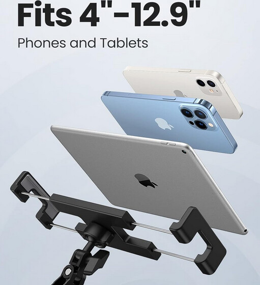
Something like this (except the FW12 probably has the same vertical length as my monitor)
What would be really cool though would be a VESA mountable dock that I could just slide it in to and have it connect to one of the usb-c ports, similar to the switch dock except the screen needs to be visible. That would probably require some 3d modeling and stuff which is well above my paygrade, but maybe that could be a fun learning project.
I’m not expecting this to work with the FW12, but it’s helped me see a bunch of important use cases:
Easily off-and-on-able
Need to be able to be removed from the mount easily
Stable but movable arm
So to use it as a touchscreen/drawing pad it needs to be stably mounted on the pole, but movable for different angles
Arm should be able to be brought close or pushed right back, or variants in between
Cables!
Don’t forget cables, some way of making them disappear as much as possible behind the bracket
I’m in Batch 9 Guild and as soon as it arrives (expected late sept by this point) I’ll be working something out to fit it onto my monitor arms.
I’ve started thinking about this too much, clearly..
Had a dig around on the various frame.work pages for the FW12 and there’s not much on the dimensions other than the big width/height/depth as the Hardware development tile on [FW12 Resource and Guides](https://frame.work/gb/en/laptop12?tab=resources-and-guides) is showing GitHub repository coming soon…
…so I loaded up a BUNCH of tabs of FW12 images and made a rough but usable SVG from them:
This forum doesn’t support SVG, so that’s a jpeg.
The base is blank, no vents, nothing, so I’ll start thinking about how I can ‘hold’ onto this, concerns I’ve got are I don’t want to clamp the width too much, that’ll apply weird pressures on the hinges. I don’t want to clamp top/bottom or side/side as I don’t know the compression tolerance of it yet, but I’ve got something to look at and ponder at least while I’m checking emails for the order status
(Just the first one I found; I don’t know anything about the company.)
In general I’d take advantage of the bezel space.
With an edge-to-edge display you have to clamp from the side or you obscure the screen.
With bezels you can wrap around to the front of the screen a bit without being in the way, which should make it easier to hold the FW12 securely without putting much force on it.
Just be mindful of the thickness; lots of tablet mounts are designed for a thinner device.
Sure that’s doable and if you buy and measure the USB hub for me, we can make the hub snap in without glue. Do you have access to a 3D printer? I made sure the design fits on an A1 mini
Okay cool, yes I already have the hub, since it’s an old one my wife doesn’t need anymore.
However I won’t have my FW12 until October because it won’t arrive until I have to leave. I could give you the measurements right now I just don’t want you to waste time without me knowing if the dock actually works on my FW12.
Edit:
I just found out this week that one of my friends has a printer. I’ll ask him what size it is and what material he can print.
Easy. Also I have a FW12 myself, so I can confirm it fits. I just don’t have the M4 hardware to actually put it on my monitor stand. I’ll model in the cable holder for you. Let me know if there’s any other details you want me to change about the mount.
The only thing I am not sure about at the moment is how I would route the cables and if I would want the usb-c hub attached to the back somehow. with that though then it might be better to get a usb-c hub with a 90° angle or something.
For now, I’d recommend just double sided taping the hub to the back of the vesa mount. Also I think I should redesign the mount so that it attaches where the middle of the laptop would be. This would make it print in multiple pieces. I’ll get back to you when I’m done.
I was just thinking that maybe holes should or could be made so that the speakers still work?! And maybe the headphone jack as well? They are on the sides after all, right?
Edit:
Don’t get me wrong, I am very grateful of what you have done and I think it’s amazing, but I am somebody who always tries to improve things. Hence the suggestions.
I’ve updated the Printables post. There’s now a cable holder and everything. You just need some M4 hardware. Should be good to print now.
I’ve done some test prints and confirmed my dimensions are correct but since I didn’t print the whole thing at once, I haven’t included a photo. If you do end up printing one for yourself, please share the photos so I can add it to the Printables page.
No particular settings. Use whatever infill you want but perhaps set perimeters to 2 or 3 depending on how much strength you want (perimeter count will affect part strength more than infill patterns). No supports required.