When I had to decide between getting the AI 370 and the 7840U it was essentially between the higher TDP (and hopefully less throttling) and the better GPU in the 7840. I decided for the latter and after replacing the stock paste with PTM7950 thermals were ok, but things got a little bit too toasty after I found out about ryzenadj, especially for the VRM.
Found this thread by chance shortly after and took the gamble on a 50€ heatsink with 12€ shipping, ouch. My “brother” @Benn was a little quicker with his test, but I figured it can’t hurt to have two independent ones, so I did mine a few days ago.
Test setup:
- framework 13 7840U, 2x16GB RAM 5600MHz
- angled on stand for better airflow, no external fan
- Linux Mint 22.1, Cinnamon 6.4.8, kernel 6.14.0, bios 3.09
- cpu testing: s-tui 1.1.6 + stress 1.0.7
- gpu testing: amdgpu_top 0.10.5 + furmark 2.9.0.0
- tweaking with ryzenadj 0.16.0 (last release is broken and non-sbu version)
- default:
sudo ryzenadj --slow-limit=30000 --apu-skin-temp=60
- battery at 90%, power supply plugged in, set to performance
- all tests at steady state (system warmed up at least 10min at high load)
- all tests on temperature rise (pause preheat for 15s before starting test - this give more consistent results)
- ambient temperature about 30°C. I did the tests after one another, there might be some ambient temp drift
- after applying new PTM7950, the system was thermal cycled a few times to allow the material to spread
A few general observations first:
- most tools require sudo for full information; s-tui needs latest kernal to show all sensors
- focus on CPU testing, GPU testing incomplete
- that said, I could not hit max clock rate on the GPU, even at 43W no CPU load
- microstutters in 3D applications are related to X11, perfectly smooth on wayland
- RAM gets to over 85°C when using GPU. I added thermal pads between the sticks and the bare board, now its about 65°C
Test 0: 7840U stock paste vs. PTM7950
Foolishly I did the first test in normal mode and only have a couple notes. In normal mode the peak power limit is 50W peak for 3s, 35W short term (30s) after which it quickly falls of to 28W sustained.
|
mode |
power |
all core |
temp |
| stock |
balanced |
27.7W |
3.2GHz |
85°C |
| ptm7950 |
balanced |
28W |
3.37GHz |
78°C |
| ptm7950 |
performance |
30W |
3.44GHz |
80°C |
So just switching out the stop paste for cheap aliexpress PTM7950 improves temps by 7°C at 28W! Crazy how better temps give you a 5% clock boost as well, just because the chip runs a little more efficient at lower temps. The fan sounded the same, but I did not have a fan rpm measurement at that time.
Thermals:
This nice thermal image was taken after running 30W sustained. You can clearly see that the two VRM chips next to the CPU are the hottest, the upper one running at 78.8°C surface temp. Its core temperature will be a bit higher, but its also rated at 125°C max, so no problem.
When talking about cooling solutions, temperatures are not the best metric, because they vary with power throughput. The better value is thermal resistance, it how much temperature increase per watt of power throughput. On top of the CPU we measure about 56°C, so the delta to the on die sensor is 24°C and the thermal resistance Rth is 0.8°C/W on this first section.
On the cooling fins we measure an average of about 54°C and 55°C, the difference is 2°C and 1°C respectively. Because the pipes are identical, we can assume the Rth is identical and therefore the increased difference means a higher power flow on the inner pipe. This amkes intuitive sense, because the inner pipe gets cooled with outside air, while the outer pipe gets only the prewarmed air. Assuming the 2:1 ratio this means the pipes have an effective Rth of 0.1°C/W.
Finally at an ambient temperature of 30°C the cooler fins have a thermal resistance to the ambient air of 24°C/30W = 0.8W at the given airflow. The nice thing about the Rth values is that you can also add them up and use the sum for end-to-end thermal calculations:
Rth_sum = 0.8 + 0.1 + 0.8 = 1.7°C/W
T_diff  = Rth_sum * Power = 1.7°C/W * 30W = 51°C
T_CPU   = 30°C (ambient) + 51°C (T_diff)  = 81°C  (1°C rounding error)
What I wanted to highlight with this exercise is that the heat pipe is already almost perfect and cant be improved much. What we can du however is reduce the thermal resistance into or out of the pipe.
Test 1: 7840U 43W sustained reference
Before swapping the the AI 300 cooler I wanted a reference number and internal temps. As stated before, I did all tests with s-tui. Run it with sudo to get all the sensors. Your view might vary slightly because the SSD and WiFi card have their own sensors. You can clearly see that all graphs are steady state, and the left side provides a detailed numeric readout.
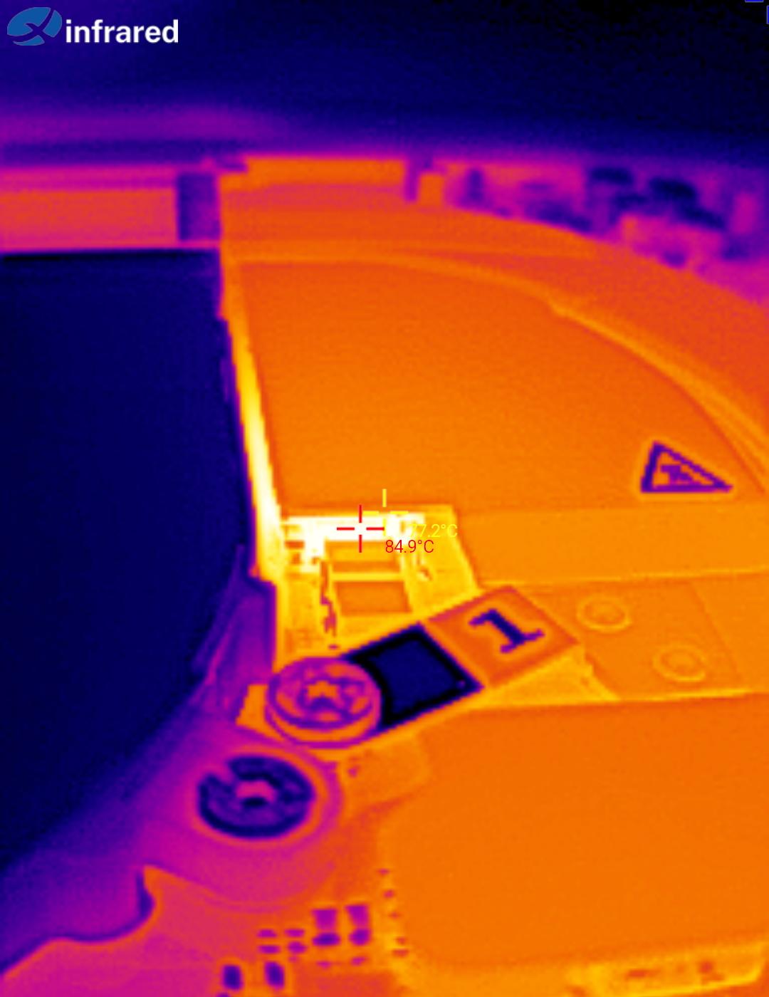
Yes, I was able to hit 43W with PTM7950. But no, its not a good idea, because it is cooking the VRM hard with 98.8°C. With some delta to its internal temperature, closed lid and circulating heat form internal components (NVME, RAM) the margin is too small for my liking. The surrounding parts won’t like the high temperatures either and may age at an accelerated pace.
I would suggest aiming for 85-90°C VRM temperature for continuous operation, which is reached at about 35W CPU power. Unless… we cool the VRM too.
Test 2: AI 300 stock paste
Eager to see the improvement I swapped coolers and I started with 43W. The temperature hit the ceiling immediately and I hastily dialed back the power. Not a great start, but I could be doing something wrong. Anyway, I took test results at 30W and 35W.
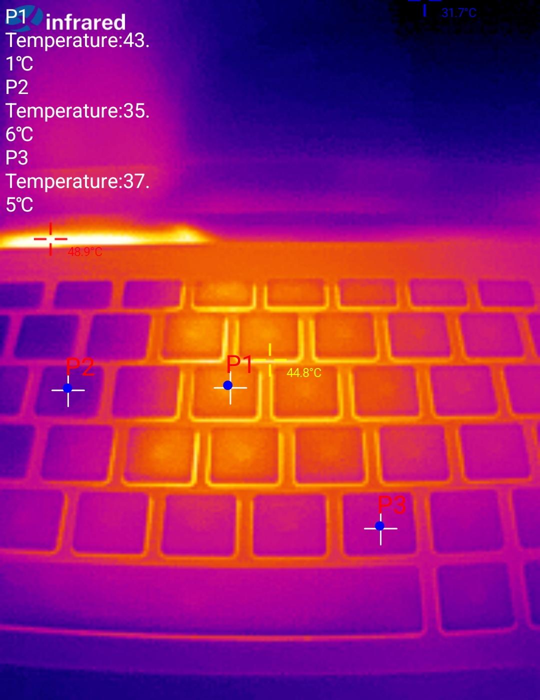
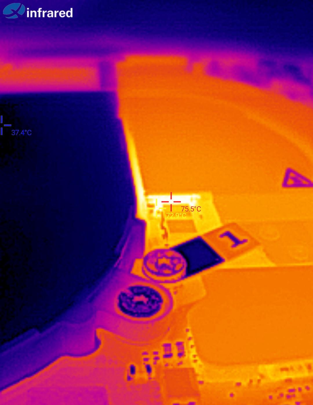
Thermal cam images (30W) aren’t that promising either. The keyboard heated up to 45°C in the seams and 43°C on the keycap, compared to the normal temperature of 35-37°C. The reason for this is that the fancy VRM cooler touches the underside of the keyboard, or at the very least in is close proximity. The VRM is doing better then before, but only by 3-4°C. I also noticed a hotspot on the contact plate next to the heat pipe and measured that at 72°C.
Lets quickly calculate the thermal resistances to the other cooler. Its not super scientific, but at least should give an idea what contributes most to the worse result:
Rth_cpu = 25.3°C/35W = 0.722°C/W
Rth_pipe = 0.8°C/35W = 0.022°C/W
Rth_air = 35.7°C/35W = 1.02°C/W
This new cooler design has a much worse heat transfer from the pipe to the air. I suspect the issue is the strong gradient of 10°C across the heat pipe to fin contact area. I wonder if this can be mitigated by changing the fin geometry with longer or denser fins to guide the airflow better. A similar approach was taken on the 5090 flow-through cooler.
Test 3: AI 300 PTM7950
Maybe the stock paste is not the same phase change material? I took of the heatsink, cleaned of the paste and noticed contamination on the copper. This was a very thin but hard residue, which I could not wipe off. To give it the best change, I lapped the cooler to a mirror shine.
Yet, even with a polished contact area and fresh PTM7950 results look the same within the margin of error.
Test 4: AI 300 no VRM
So what if the VRM adds to much heat into the system so that it can’t cool don’t the CPU effectively? Easy test, just remove the pads and reinstall. The issue persists, but at least this proves that cooling the VRM doesn’t make things worse.
Test 5: 7840 with VRM
Now that it is proven VRM cooling does not harm performance, I figured I can attach an extra copper fin to the heat pipe. I did have some 1mm copper sheet, I cut of a 7mm wide strip and carefully bend it into a flat Z shape. I isolated it with kapton tape except the thermal contact area. Right now it is attached to the heat pipe with shitty thermal adhesive tape, but I plan on soldering it later for reliability. It contacts with VRM with 2x 1.5mm pads stacked. And as the thermal image proves, this worked!
Performance of the AI 300 heat sink
Its a bummer that the new heatsink performs worse then the old one. Now I don’t have a AI 300 board to test the 7040 cooler on, which would be a reasonable follow up experiment. I did notice that the 7840U die does not sit perfectly center under the heat pipe, but still the entire chip is covered and in comparison to the other cooler it does not have the “gap” between the pipes.
If this is expected behavior, then I really wonder why framework didn’t stick with the old design. Is one wide pipe cheaper then two small ones? Does it look more impressive and like a sell-able upgrade? Or is it just as unexpected for you as it is for me? In which case I how you are happy with my hardware bug report 
Oh and one more thing now that I have the attention: The VRMs do have a hardware temperature output signal which is digitized by the power stage controller. Can you please add the reading as a sensor to the EC controller? It would help a lot. Alternatively you could also convince MPS to hand out a datasheet and register map so we can attempt our own I2C driver for that.