Another week another update!
Not much happening on the physical front, this week and weekend was mostly a digital endeavor.
I part picked everything for the tilt mechanism: went with an Arduino Nano Every, some limit switches, a 24v 40rpm worm gear motor assembly, BTS7960 motor drivers, LEDs, buttons, etc, etc… more to come on that later… but parts are ordered and most are in.
Also did some preliminary calculations on the gearing for the tilt mechanism… turns out to get reasonable gearing… I’d need a 2 foot diameter gear which isn’t practical, so I’ll have to go with a series of gears to have a pinion gear on the motor, a compound gear in the middle, before going to the final gear piece on the manta body. 25T → 75T direction attached to a 20T → 100T on the manta ray.
And now for the fun pictures!
The reservoirs exist in CAD as not just mock ups:
With a volume of 3.4 liters, so I could fill the system with a full gallon of coolant
The mounting for the reservoirs isn’t completely done, but I do have the hook-ups modeled:
I know this sounds crazy, but I should be able to 3d print those on my H2C in ABS-GF. I modeled up a test piece, screwed it together with just a 2mm o-ring sandwiched in, and it held water. Also that’s with ZERO post processing, so with some mild post processing I’m feeling pretty confident I can make a seal between ABS-GF parts. I wanted to use polycarbonate or regular ABS, but the shrinkage is just too high.
So yeah… not much else to say, but here are some side profiles of the work in progress. It’s a little bit THICCC, but I think it’s not bad.
1 Like
I appreciate you sharing this. I’m a little nervous that things will be assembled and just not work. I’m hoping to model up the top of the CPU block and mounting very soon because I NEED to test this sooner than later.
So I’ll have a real update tomorrow… but WOW yesterday and today were an emotional rollercoaster… Finally got the thermal paste I wanted to use, loaded it up with the shim and waterblock… and computer wouldn’t boot.
LED1 lit
press power
LED2 lit (and light on powersupply would go blue)
8 seconds or so later, both LED2 and powersupply LED go out.
Hours of troubleshooting… unplug everything, replug everything, swap back to aircooler… Nothing…
My fiance comes in to see what’s going on, I explain it to her, show her, LEDS go out… and while we are talking LED3 and LED4 spring to life.
Eventually I get it posting again… I put the watercooling back on, it posts again, go to load up any test to get temps… and it’s AWFUL just as you thought… but I can play a few rounds of Bloons TD6, anything more than that and it gets up to a full 100C…
I shut it down for the night. I tested it again during lunch today… same thing but temps seem a little better… shut it down again… I come back after work to actually get screenshots and BOOM, temps are actually pretty good now… I’ve had Unigine heaven on a loop for the last 2 hours and it’s sitting comfortably at 52C with 100% utilization on the GPU, while boosting happily all the way up. Even stress tested Unigine + P95 and was not hitting limits…
I’m using Thermal Grizzly’s Kryonaut Extreme, supposedly it doesn’t have a break in period but I guess it does? that or the thermal pads were too thick and took some time to settle? I HAVE NO IDEA… but the waterblock + shim is working.
Ironically I think I know the heat issue: I had to change my connector for my test pump… and I had a bad crimp. I went to plug back in the graphics card and usb card and noticed my pump’s power connector was fickle, so I think the pump literally wasn’t working.
AFAIK the RAM uses a little under 2W/chip at full power (a large % of which will be conducted downward
that is true, if you know how to use SPICE/LTSPICE, you can simulate it.
when temp rise, (thermal mass buffer = rate of rise) you can imagine the temp line going up, at some point the top side will “give way” and start sucking heat.
sure more heat may go thru bottom **initially ! because it is at room temp
you just need some specs and some tweaking. because pcb side the heat is stuck, it is not actively cooled. the temp will rise and therefore as time pass, less heat will go thru bottom.
i was thinking, those 2 big wings could have been a really really big thermal exchanger for the fluids. how big is it ? 1 square meter ?
my first impression of seeing the manta shape wing = wow big heat sink !
** ahhh my god, i was about to hit buy a desktop, it is sold out ! WHHYYYYYY ??? 
The mainboard is not out of stock
Honestly putting it in a different case with a HDplex GaN PSU is not a bad option at all..
I’ll have to get the surface area of each wing from CAD… but I’m cutting them out of 10 inch by 16 inch pieces of aluminum stock…
Each reservoir is basically a stack of:
Acrylic window
Reservoir Shell
Aluminum “heat” sink
and the reservoir “shell” that I’m printing is 320mm wide by 300mm long and they are about 14mm thick if I recall.
So closer to 2 square feet of surface area… but I’m carving channels into the aluminum to increase the surface area on both the water side and the air side.
2 Likes
mmm its true i guess i could simply cobble together the “parts” 
*** ok i made the order. so i guess im gonna have to “join” you and make a “frame” for this thing now  … i dont think it will be a manta
1 Like
Ok after averaging something like I believe 50 hours a week (while still working 40 hours a week) working on this the two weeks leading up to Quake con I was pretty dead. Sorry for the lack of updates, it was REALLY down to the wire, but I did make it to the event with a working computer! I took photos so here they are!
So where I left off I got the CPU block mounted and had cooling issues, I’m confident that my connector my pump I was using to test was flakey, I fixed that and my test set up worked just fine!
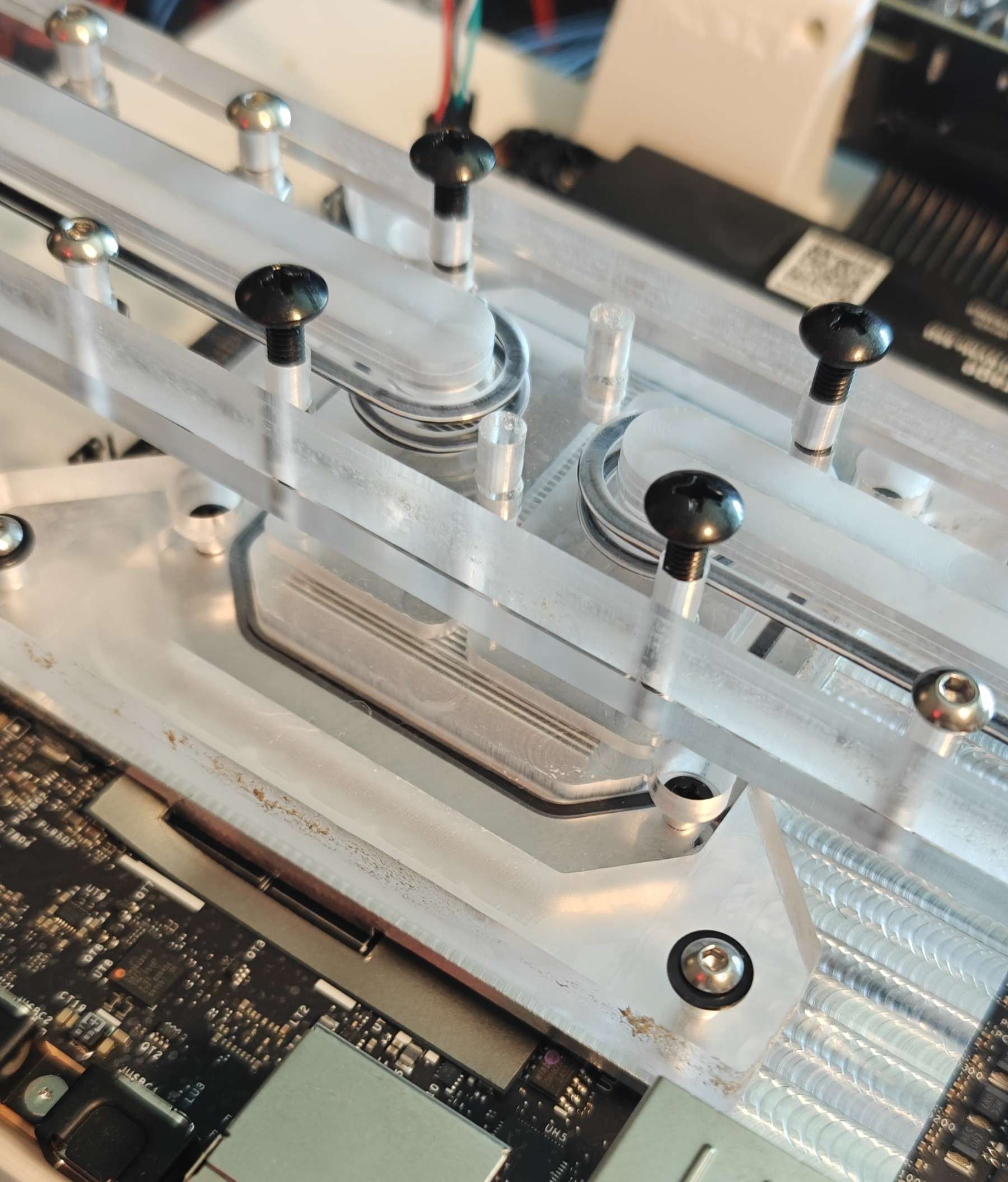
I went to install my distro plate to the top of the CPU block for a test fit and realized a pretty critical problem:
I forgot the 24 pin and 8 pin connectors were between the CPU and the PCIe slot… I did not leave myself clearance for wires:
After some mild panic, I found an option on amazon, and re-cnc’d a cpu block that was 5mm taller and a few days later I had wires that worked!
1 Like
Next step was to get the reservoirs existing in real life. I really maxed out my printer with the “shells” for the reservoirs (120mm fan for scale):
And began CNC’ing the back walls. I didn’t just cut out the shape but also cut channels into them to give me increased surface area:
Turns out turning aluminum into shavings makes a lot of shavings:
But they came out pretty good, had a bit of chatter around the edges, but not bad at all:
They fit on the shells pretty good too.
1 Like
I finished up the core of the body and finally got that printed in the correct filament (everything structural was ABS-GF. I once again REALLY maxed out my printer, in fact my CAD files were 322mm wide and my printer can only do 320mm so I had to shave off 1mm on each side of the core, but it’s ok because there is an intermediate bracket that attaches the wings to the core.
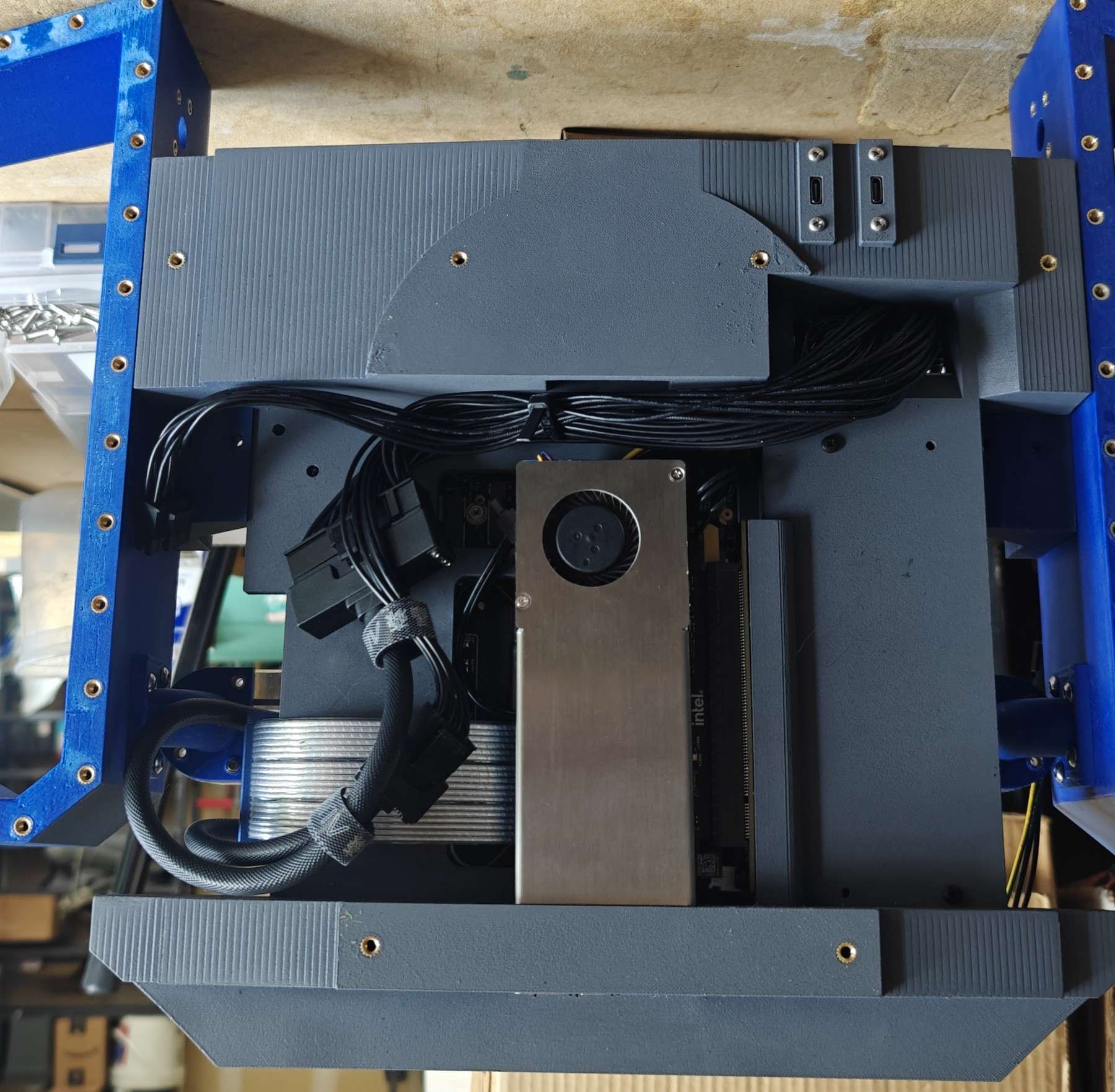
Installed the electronics:
Managed the cables:
(I really wanted to do custom cables but both the extensions and running out of time prevented me)
And went for a dry fit:
A reminder that the point of this computer is to have a linear watercooling “loop” there is no pump, the computer tilts back and forth to drain from one reservoir to the other so the cross section of the watercooling is literally:
1 Like
I don’t have great photos of this process because a friend was helping me while I was working on sanding and painting. I laid out a large piece of glass and was lapping the “top” and “bottom” of the reservoir shells so I’d have a good surface to mate with the aluminum and acrylic. Also all of the 3d printed plastic was painted that wasn’t a mating surface or the inside of the reservoirs. My friend handled the cerakote on the aluminum pieces, this was critical because aluminum and copper do NOT get a long chemically in a watercooling setup… Well I guess you can say they get along too well? Without the coating to prevent corrosion the aluminum will literally migrate through the coolant to the copper.
So at this point the top or inside of the aluminum wall is a deep blue and the bottom or outside is a nice gray. And then we got it mounted up to the shell with some rubber sealant:
The I cut the acrylic fronts and got those mounted up too with a rubber o-ring:
1 Like
Then I got it all mounted up again on the stand and did some tilt testing:

JUST LOOK AT THAT FLOW! Honestly that’s WAY faster than I was expecting
1 Like
At this point I leave in 2 days I think and I haven’t even packed. So it’s a mad dash to the end.
I finished modeling up the head and printed it:
I also modeled up the butt/tail section, got them lightly sanded, printed, and installed:
Removed the head and tail, loaded it up and hit the road!
Next post will be in a few days to a week and I’ll talk about how I did and share some final photos/videos.
2 Likes
I went with just distilled water with some additive. I also didn’t have time for figuring out RGB so I had a plan at this point but it was a bit of a gamble.
Oh and I didn’t even talk about the last two panels I made before I left it was a blur. But I’ll give you a spoiler, we brought a projector 
My explanation was that manta rays don’t have bioluminescence aka glow. But something needed to light it up in the BYOC because otherwise you got this:
And don’t worry it looked A LOT better than that
1 Like
hmm, it needs some soft light features, im imagining sun coming thru the sea surface and bouncing off the back, like waves of random light in this pic ?
but that would mean a matrix of small leds, very complex, doable on flex substrate. but complex . i dont suppose you gonna project video on the (ahem) 
I mean, the computer already requires an external tilting mechanism, why not just fully commit to the art installation bit?
- It did look AMAZING, quite stunning imo
- I’m pretty sure 2 of the 5 judges HATED the art installation idea
Framework did a post on instagram about it:
https://www.instagram.com/frameworkcomputer/p/DcbjIPDlHAF/?hl=en
1 Like