Greetings.
After realizing the sub-optimality of conventional keyboard layouts around 3 years ago, I became kind of a die-hard for ergonomic keyboards.
Laptops unfortunately do not leave much choice when it comes to keyboard layouts and customization, so I have been reluctant to purchase any recent laptop products, despite losing my main laptop four years ago, using a university loaner instead.
One of the key factors that made me go for a FW laptop was the openness of the system, especially around the parts and components, which at least gave me a glimmer of hope that there could be something done to fit the keyboard to my personal preferences, namely a columnar staggered key layout, with thumb clusters.
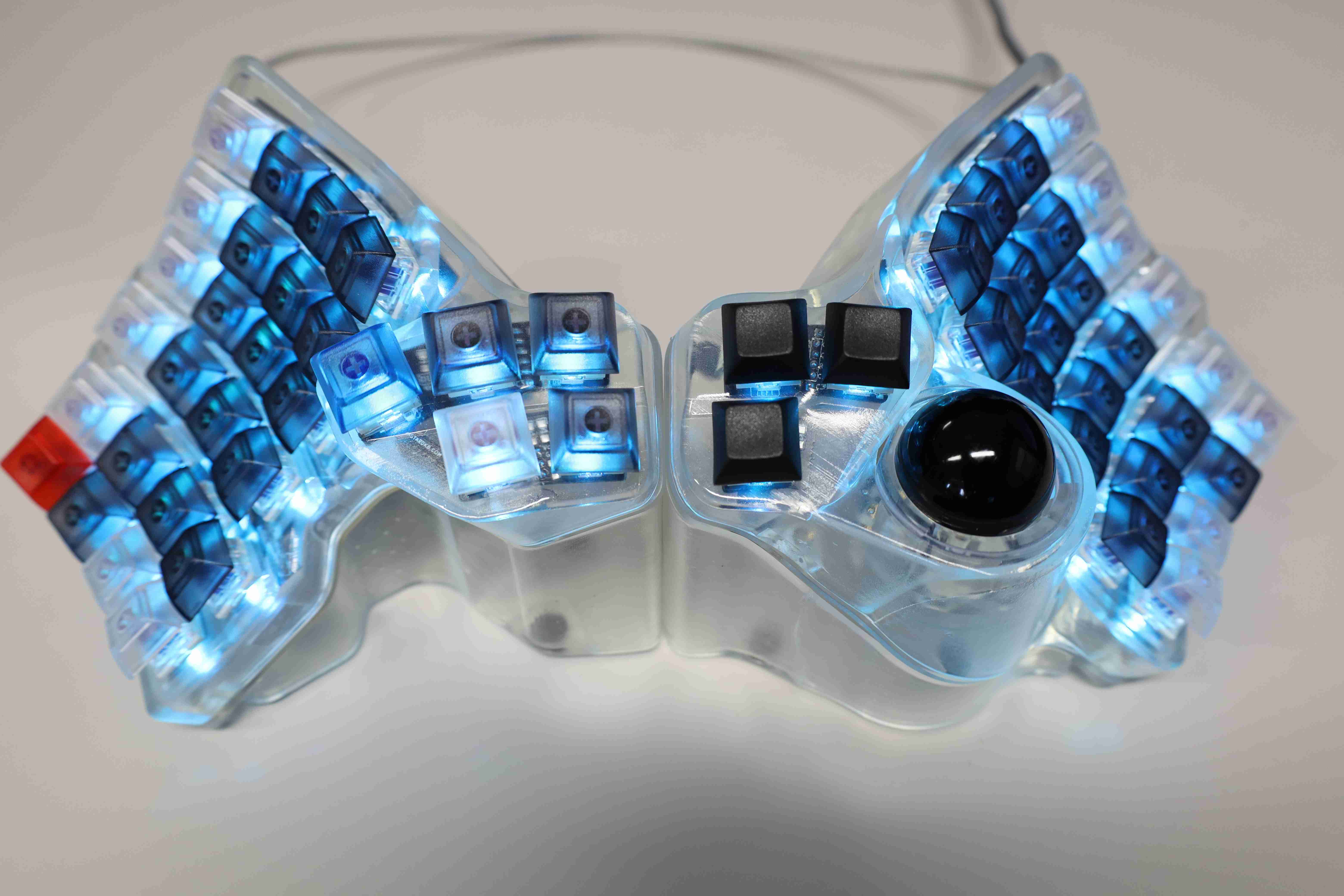
Hence this project of DIYing such a keyboard, albeit only a prototype for now:

From this post, the main challenge is the height of the keyboard being 3.8mm, which leave virtually no room for mechanical key switches, ubiquitous for DIY mechanical keyboards.
There might be some hope with the Cherry MX Ultra Low Profile, but it does not seem commercially available as of now which can now be ordered here. Getting some samples to experiment with.
The lowest profile keyboard switch I could put my hands on was these [Khail PG switches], but the height from the key cap top to the legs is already 6.5 mm.
The only possibility I could think of was to re-purpose the laptop’s keyboard itself, manually re-arranging the layout somehow. Unfortunately, since I now daily drive my FW for work, I could not directly experiment with the input cover and keyboard.
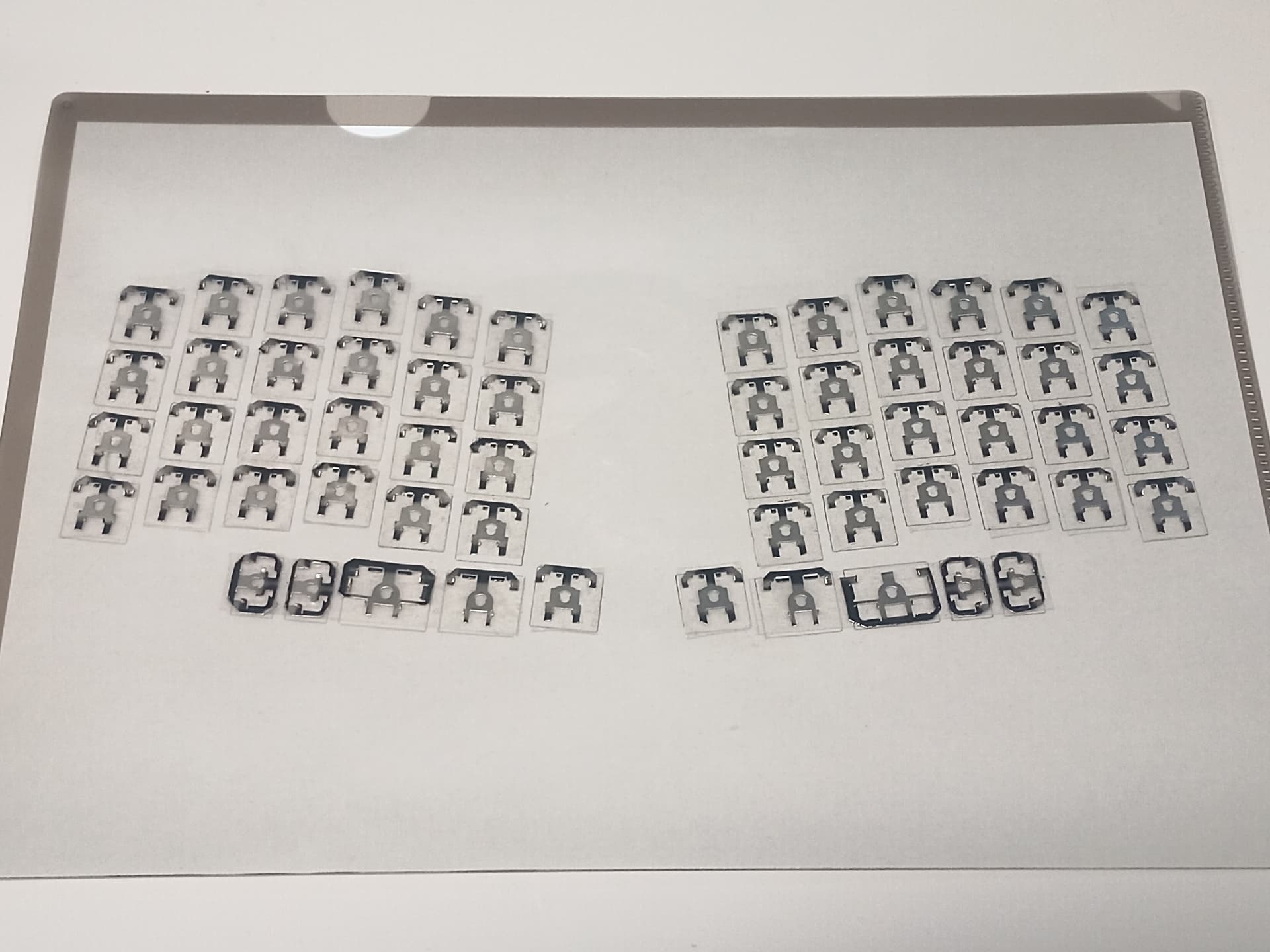
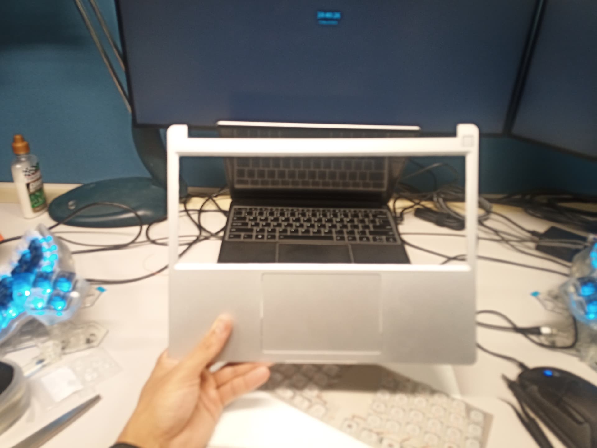
Instead, I went for the cheapest and thinnest external keyboard I could find, to get some thin enough switch samples to experiment with, as well as understand how the membrane-based keyboard matrices work, with the ultimate aim of reproducing it.
The first step was to check if it was possible to design a base receptacle for the key switches.
Measurements of the reference receptacle and the key switches “legs”, and some CAD prototyping resulted in a 3D-printed based receptacles that allow the switches to be placed and used on the reference keyboard.
Unfortunately, although the key switches from the Artek keyboard are relatively thin, there are still a bit too thick to be directly integrated into the FW anyway, so I have only made the right half of the keyboard to save up some time and 3D printing material.
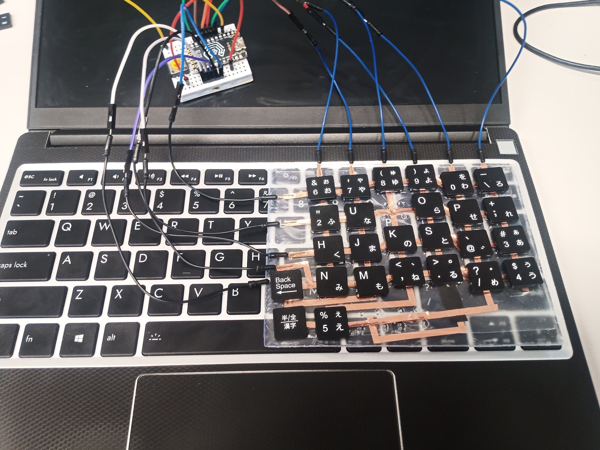
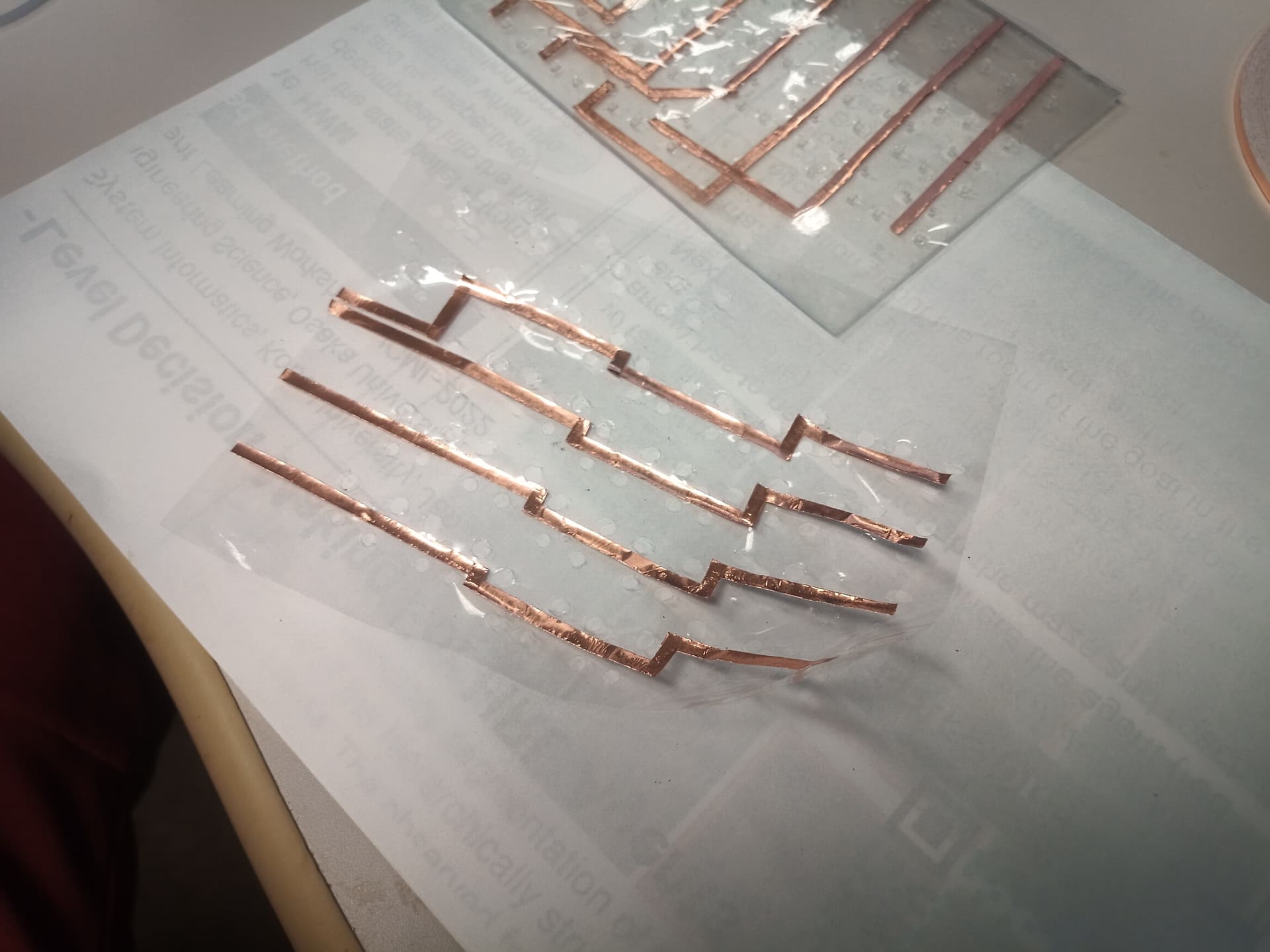
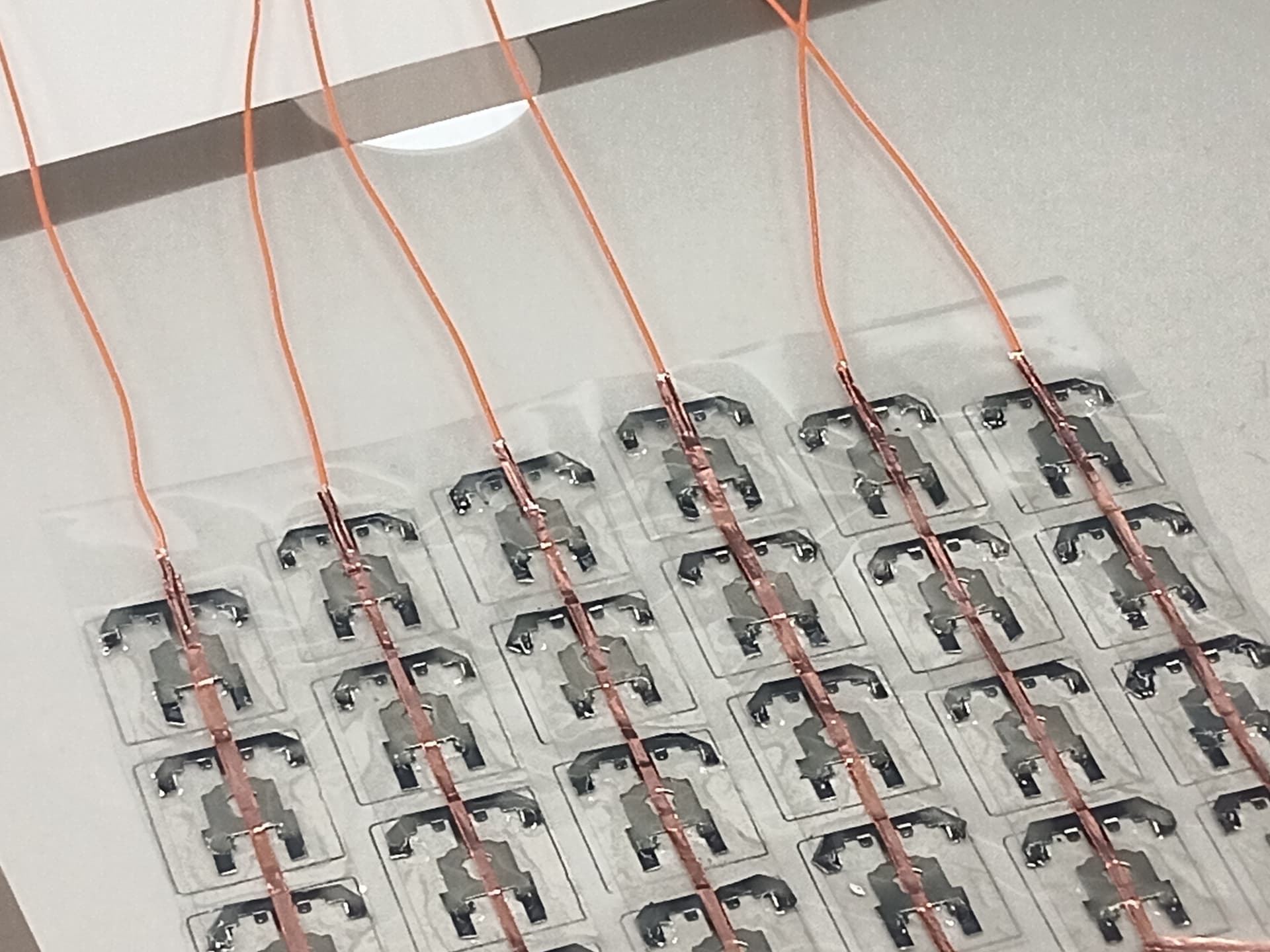
That half was then used to prototype a keyboard matrix that would be compatible with the membrane key switches.
The matrix itself was designed using a thin, double-sided copper tape, laid onto 6 columns and 5 rows to handle the 4 * 6 + 5 = 29 for the desired layout.


For testing the usability of a keyboard, the columns and rows are connected to an Elite C to run QMK, which I am more familiar with to design and flash custom firmware.
This prototype is just a half size, and there are a lot of jumper cables sticking around, but the final product will still be clean and thin enough to match the 3.8 mm limit of the FW keyboard.
To sum it all up, this half prototype was to sanity check two points:
- check the feasibility of printing small receptacles for laptop keyboard scissor switches.
- check that the DIY copper tape matrix can be used as a functional keyboard, testing with Elite C.
The future road map would be as follows:
-
Save up enough to order a spare input cover and keyboard from the marketplace, so that I can keep using the laptop while working on the final version. EDIT The amazing Framework Team has provided two input covers for experimentation. Currently disassembling the keyboard and studying its part to hopefully come up with an alternative that matches the desiderata in this post.
Similarly to how this prototype was made, the keyboard will be disassembled and re-arranged into the desired layout.
The grid of the top cover will be cut, and probably replaced with a 3D-printed top cover grid that matches the custom layout.
A few challenges on this part:- The keyboard assembly itself is screwed into the top input cover, so there will probably be a need to add support for some screw holes into the 3D printed receptacle platform and top grid.
- There might be some overlooked details regarding the shape of the keyboard assembly and how it fits into the whole laptop, but I hope to flesh that out once I can go deeper into the spare input cover.
-
Further fleshed out the 3D printed case receptacle, or maybe look into something even more reliable, like a custom-cut aluminum frame.
-
Further improve the copper tape-based matrix, as the one designed for the prototype ended up becoming quite fragile and unreliable after some use. Alternatively, find a way to combine the rubber switches of the original FW keyboard, and some very thin PCB. The latter would allow easier setup of diodes.
-
Investigate the potential problems of key ghosting and other matrix based (no diodes) problems: either a thin enough PCB that will still allow diodes, or manually installing diodes on the copper tape ? Or any other software solution ?
-
Regarding the interface between the custom matrix and the FW main board / EC: the original idea was to use an Elite C loaded with QMK firmware because of the latter’s ease of use, a plethora of features, and customization. The Elite C would be internally connected to the motherboard. For example, through one of the recessed USB C where the expansion cards are plugged in. As a workaround to losing one USB C port, there was also the possibility of having the USB C expansion card that is essentially required for charging be upgraded to something like this double USB C card, but with one of the port being internal. However, it looked quite difficult to implement.
-
Instead, the idea is to use an FPC adapter and a flex cable just as the default FW keyboard to connect it directly to the main board / EC, and re-write the EC’s keyboard code to match the custom design. This would be the cleanest method. No expansion slot loss, and close to factory integration.
-
The final challenge would be to design a custom firmware for such a keyboard, that can be persistently flashed onto the FW’s EC.
Although I only had a cursory glance at the source code, it should be done once I get familiar enough with the current implementation. Hopefully, I can make it handle more than just the default FN layer though.
I expect to need at least three (QMK-like) layers, but not sure if this can be supported by the EC. Fingers crossed on that. The physical layout has the keys for it, but I am not sure about the firmware side yet. Having some high hopes about @DHowett’s QMK-like keyboard overdrive implementation. Would greatly appreciate any recommendation or guidance on this aspect.
-


In the meantime, posting this here to get some feedback on the feasibility (especially the firmware side), or maybe some points I have not considered.
Will be posting the next updates, hopefully soon.

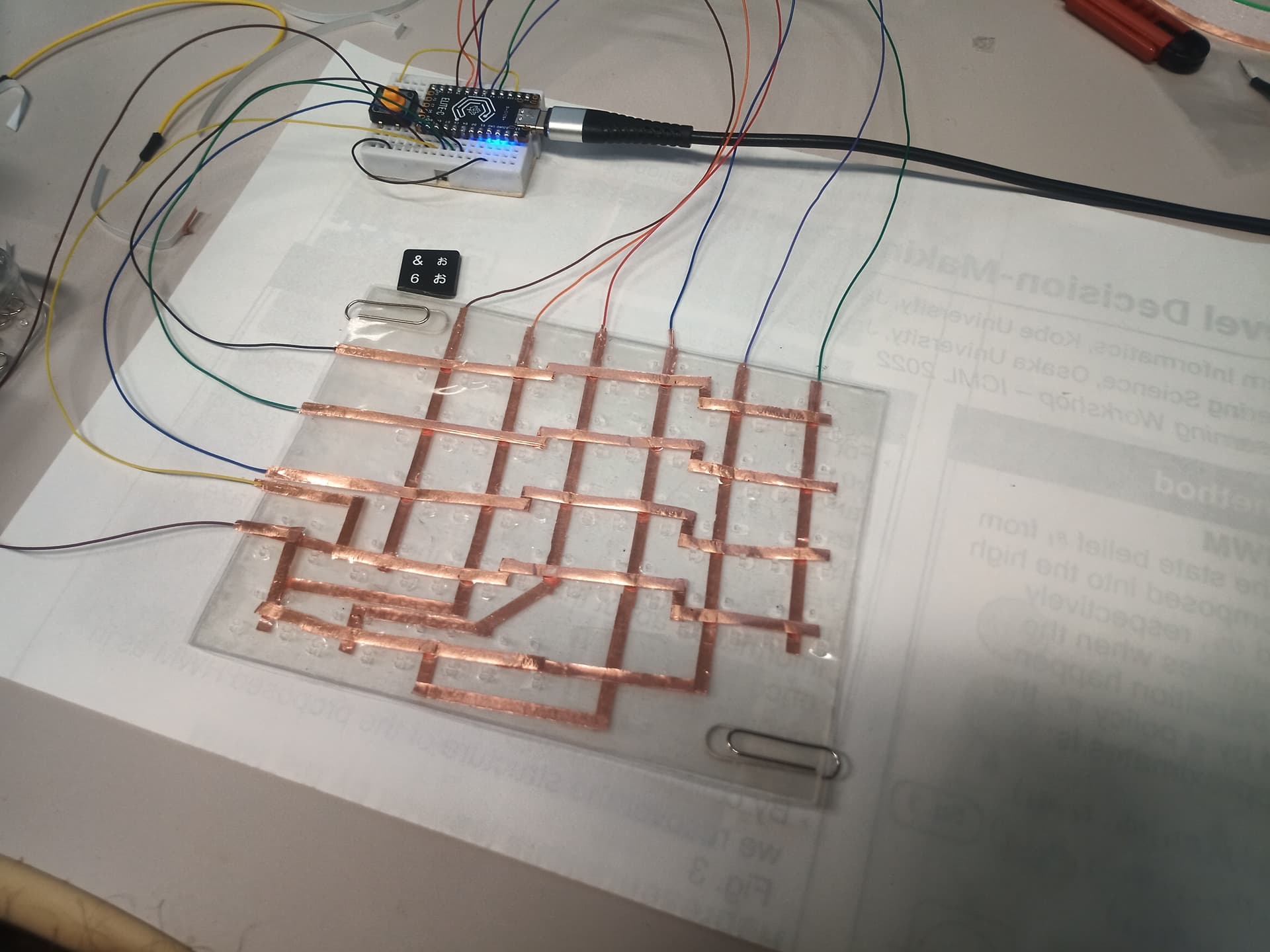
 Keyboard Prototype: Testing the matrix.")


