So it has been decided. Let’s make it happen.

On the side note, this is also useable with the Framework 13, since the 16 and the 13 use the same board side connector.
So it has been decided. Let’s make it happen.
On the side note, this is also useable with the Framework 13, since the 16 and the 13 use the same board side connector.
Niice! I thought that maybe unused eDP lanes would need to be terminated in a certain way, but found the diagram in this blog post (scroll to " Putting it together" heading) where a person left them N/C and it worked fine for them.
Pretty sure the 2lane cable in my t480s also just had them unconnected. DP does link training and fancy stuff like that so it’ll likely figure out that nothing is connected.
A quick search and apparently it is best to leave them NC.
Right. And even if it doesn’t, the display handshake should work.
well this is anticlimatic.
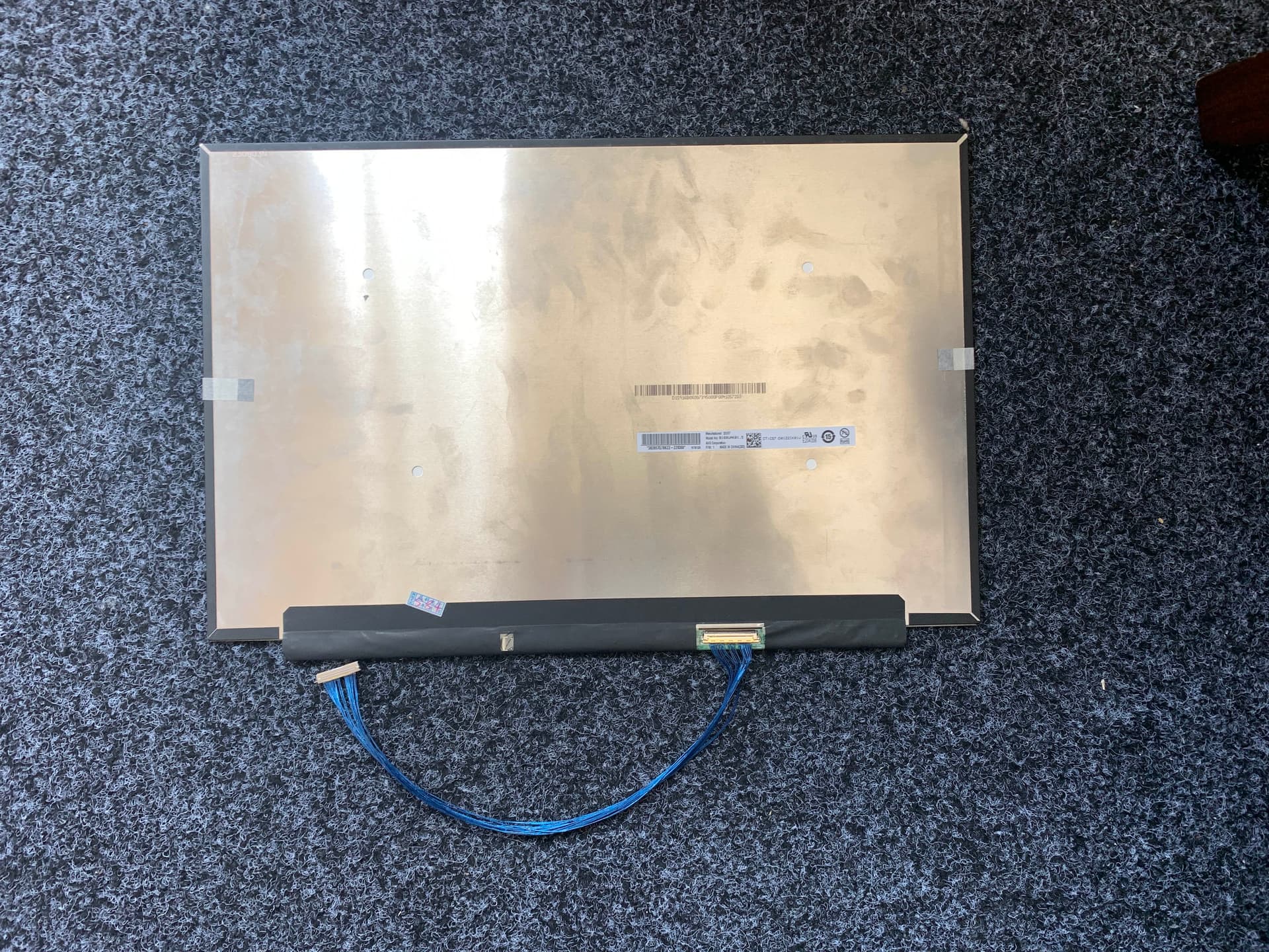
I have the cable. I have the screen. The pinout is correct (ripped apart both the framework and custom cables tape for analysis)
Hooked up to the main board, and uh … nothing
No spark, no like, magic smoke or whatsnot. Just nothing. Laptop works, post to external display.
And if I swap back the NV160QDM, the laptop works.
So uh. No $1000 mistake. $100 mistake. Big deal. At least I cannot destroy the main board. Mostly.
I can probe the screen for power, but I might also just short something in the process. I can, however, continuity check the voltage pins and ground pins to see if I messed up the cabling.
I heard someone have modified EC code that support debugging, I might need some of that.
(makes spark with multimeter)
Ooo! But like, I am in voltage measurement mode?
Probably contacted the back, lets try that again. yeah it reads … 15? Sounds about right.
I have some POST code. Let’s read those!
1st code:
WGGGGGRGGGGGGOBBBGGBGG
2nd code (no display connected):
WGGGGGRGGGGGROGGGGBBGG
3rd code (UAK01.5 connected):
WGGGGGRGGGGGROGGGGBBGG
I dont think I even need to look them up. The internal display bit is failing, and the code is exactly the same.
What even handles link training? bios? ec?
Apparently there is a bit more to this story.
In Linux, if you connect the 160UAK 01.5, the screen (on the external) freaks out completely, and 1/3 of the screen goes black. And its a secondary, there is no application dock.
In Windows, Radeon 780M will be “stopped because it has reported problems.
Neither of those two issues exist if I remove the 160UAK (and just leave the eDP disconnected).
So, it knows that something is connected, but not sure what. This is a bit more acceptable outcome.
So. I suppose there is nothing we can do now? Can they help?
Occured to me that the 7040 main schematics does not have a I2C bus hooked up for the eDP.
Did you try reading the EDID?
how do I do that? Linux freaks out when I have the panel attached. It will display 2/3 of a secondary desktop on the external display
So the screen is somewhat working. Shouldn’t the rest be solveable in software, then?
You would think. Its …
Regardless of what I do, I cannot get system to display anything on my new screen. No BIOS, no nothing. I have to attach a external monitor. This inheritently has no problems with it.
However when I boot into Linux, this happens (internal no display, external 2/3rd second screen). On Windows, it will just say “Radeon 780M encountered a issue and cannot start”.
When I dont have anything plugged in, no bad things happen. Radeon 780m just work, and Linux also shows 100% primary screen (on the external). So, it knows something is plugged in, but refuse to display anything.
And when I plug the framework stock screen back in, it also just work. So i have not blown up the port on the board.
You can ask if I had blown something on the display, but i dont believe that. I custom-made cables, and I checked important pins (voltage, ground, etc).
I think the issue rise in the DP mux Framework use. The mux is 4-lane capable, with automatic link retraining. but what does it do, with a 2-lane display? And mind you the display is a DP 1.2. The mux is a DP 1.4. Probably the mux have to be configured by the firmware (or something) to do the 2-lane. This is .. not within my control, right now. I cannot see the code for the ec firmware. Perhaps because NDA is required.
Testing on the Framework 13 would be nice. There is no Mux, and it use the same main board connector. I will most likely not destroy one of those, now.
Sorry, I’m not clear on what is loading or not. Linux is freaking out to the extent that it won’t boot, to a terminal at least?
I believe all the EC firmwares are there. It’s just, they are not the easiest to find.
You’re on the FWL16, yes?
The FWL16 EC firmware is under the name Lotus. This should be the branch for it, github.com/FrameworkComputer/EmbeddedController/tree/fwk-lotus-azalea-19573
Any chance that the USB lines connected to the NC port are messing up the signal lines? It’s presumably not a power delivery issue though if you’ve checked the voltage. Anything getting warm to the touch on the panel/board? Also, if there’s any way that we can access the datasheet for the panel id be happy to take a look to see if there’s anything you’ve missed. Thanks for pursuing this though.
Yes. However I have no idea what I am looking at.
It seems like a lot of this is ChromeOS related. I see Baklava.
And while this is important, it’s 2013 chromeos related stuff.
I dont think USB lines would stall the entire display bus, no?
Furthermore I dont think the B160UAK01.5 use the USB bus for things. That’s for the touch panel.
I dont think *anything* is getting warm to the touch, which is .. good? idk. The backlight did not come on, which might suggest something.
I dont have oscilloscope to probe the backlight PWM. I suspect it might be that some part of firmware is trying to set the panel overdrive, among something else. And again, the mux problem.
How about trying to drive the panel from an external power source first then? Hook up a known good source with the exact required voltage and just use the motherboard to send data.
Sorry just read the bit about you checking the voltage is correct, my bad. Taken a look at the datasheet though: all the pins are correct on the schematic so there aren’t any shorts. First though, is the mainboard definitely sending the backlight enable signal? It seems strange that nothing happens when you try to boot it up. BTW, the schematic seems a bit strange when discussing the boot up sequence. It lists 0.5V as the max power to switch on the display, but then suggests that PWR_EN actually needs to be raised to 0.9V? Maybe I’m misinterpreting it though.
Well, I dont think that is possible. See, the pins on the screens are extremely fine (0.5mm pitch). Which is not to say that I cannot solder wires to them directly, but I would 1. ruin the connector and 2. potentially destroy something.
The display use what’s called micro-coax wires, with a ground shell outside the internal conductor. I also only have a PC power supply. And I dont think it is the problem with the power – the backlight also have the enable signal and the PWM signal.
Unfortunately not, the backlight for lcds is pretty much an entirely separate part that (appart from stuff like ulmb backlight strobing) cares pretty much not at all about what the display itself is doing and the other way around.
If the backlight is broken or not connected right it is possible it is displaying something and you just can’t see anything. If you shine a somewhat powerful flashlight at a display with a broken backlight you can usually see if it is displaying something.
EDID not reading is a pretty sub-optimal sign on the wired up right front though.