Yeah, I’m unsure either actually. It should be confirmed after I move that resistor with the general PCIe device EEPROM config from framework. If I find the time I might do it in a few hours, and if the board still works, it might be that my initial EEPROM config was just wrong. I’ll update you on that, but I recommend doing the same thing as me and just populating a 0 Ohm resistor between PEX_RST and your device’s RST pin, but also having pads available between SSD1_RST and the device’s RST pin, just in case.
I’d certainly be interested to try, but I’d love to be able to check properly before sending off another board. Please do update me - this is a really interesting problem!
According to a post from FW. The EEPROM is read by the EC. If then uses the settings from the EEPROM to configure the Expansion Bay.
One setting says to use the SSD1_RST, another setting says to use the PEX_RST, another setting is for the amount of lanes.
That is how the EEPROM controls how the PCIe interface on the expansion bay works.
Yup, that’s how it should be, so I’m leaning towards my config just being wrong. Although I might need that initial behaviour, since I do want my oculink board to be able to do 4x2 bifurcation using an oculink Y cable by just flashing different data onto the EEPROM. For regular x8 use case, this is odd behaviour tho and thats what caused issues for me too.
Looks like that even with the configuration provided by framework, the issue does not go away. I moved my 0 Ohm resistor back to connect PEX_RST to RST pin on the oculink connector and it would not work no matter what. It starts working immediately after going back to SSD1_RST. Will need to clear this up with framework since it really is such odd behavior.
To add to this, as I have already mentioned it while replying to Kieran in the OCuLink thread.
I am not using the EC firmware included with v4.02 BIOS, as I have a patch that applies higher SoC power limits using a 98W charger instead of 100W due to my Caldigit TS4 dock only exposing itself as a 4.9A 20V charger and this then results in the CPU not wanting to go full performance. So I am on the BIOS version right before v4.02 with the EC firmware that is currently in the GitHub repo.
I don’t know if there might have been changes that could affect this between the current repo state and the EC firmware bundled with v4.02, but I did want to mention it if it is relevant.
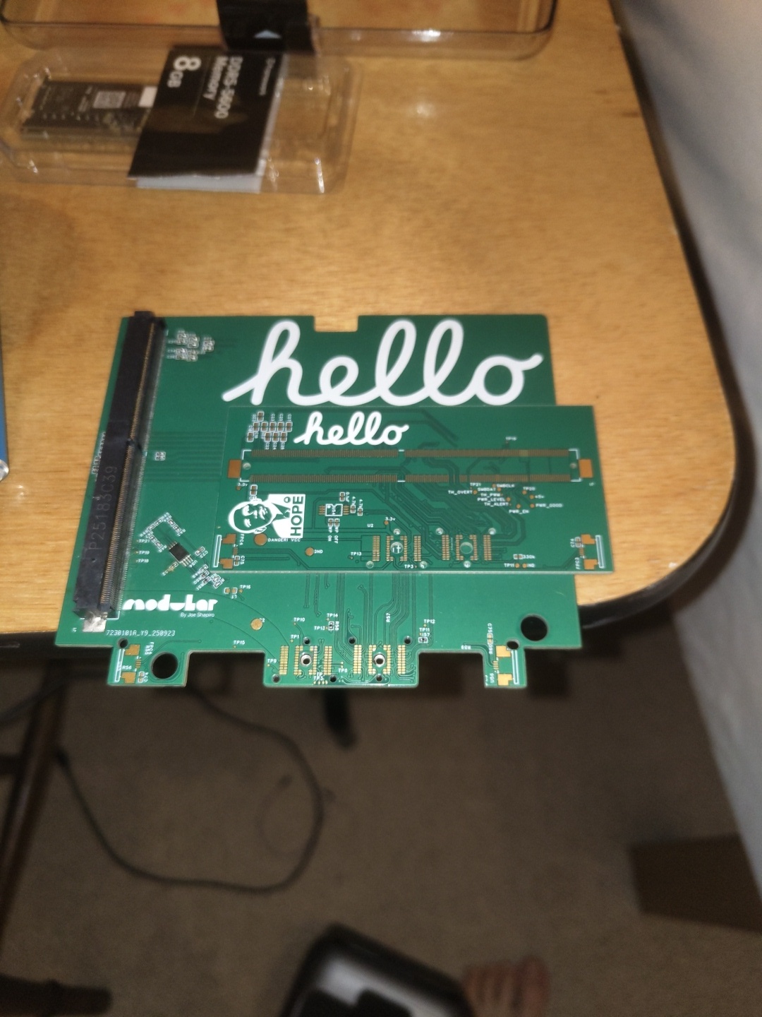
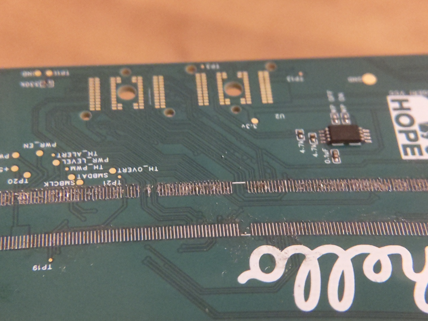
Hmm. Same old same old assembly issues. I was hoping new solder paste, (chipquik SMDLTLFP10T5), might help with some of the solder spreading, but it doesn’t seem to have made much of an improvement. To people with experience soldering pitches this small, (0.5mm): advice?
Photos below show the connector removed because of bridges and lots of tiny solder balls failing to adhere to the pads.
The temperatures are not getting high enough for the solder. Specifically, the temperature of the pcb pads and the connector pads is not high enough.
The SMDLTLFP10T5 has a datasheet with a reflow profile. Are you following that?
I guess you are up against the plastic connector, with its warping when heated too much.
Do you have the datasheet for the connector? One can then match a solder paste to the connector datasheet.
You could try to use solder paste that melts at lower temperature than the SMDLTLFP10T5. There are trade offs thought, as lower temperature solder can be less reliable.
You can also manufacture PCBs with solder resist applied between the pads.
For these difficult solder tasks, you really need a reflow oven, so that it warms the whole thing to just below the point at which the connector will be damaged, and then peaks for a very short time, just enough to melt the solder, but not long enough to damage the connector.
That was the spec that I followed, (heating to 165 degrees), but I’m concerned that the hotplate might not be as well calibrated as it claims. Finding lower temperature solder paste is certainly a possibility, but I think I’d be getting nervous about its potential to loose structural integrity at high temperatures and with the spring load of holding in the mxm card. I’ll try again with a higher temperature, and if that doesn’t work go for the reflow oven.
Slightly changing the topic - has there been any update on why Filip’s solution with SSD_RST worked? This feels like it might be the crux of some of the issues we’re experiencing.
You will need to turn the hotplate up to more than 165 to get the solder to flow properly, probably nearer to 200 or maybe even 250. Don’t forget that the PCB will be radiating heat away from the top surface, so to get the solder pads to a guaranteed solder flow temperature the hot plate will need to be at an elevated temperature.
Just tried the new fixed board, (after much faff fixing the mxm connector), and wasn’t met with much success. I’m starting to learn more about the MXM standard though and thought some of it might be useful to be more widely known.
The MXM standard is famously complex and abused by companies who lock down their own specifications, wrecking compatibility with other devices.
It’s often not enough to just have a basic PCIE link with the cards - many need to know that they’re installed with the PRSNT, (present within the machine), pins, which I haven’t hooked up to anything on v3. It should be noted though that in * ALittleWifi’s MXM immobiliser this isn’t connected, so maybe this should be taken with a grain of salt.
Some MXM GPUs are apparently just grouchy when installed into non OEM systems, as I fear might be the case with the one I’m testing with at the moment.
All in all a bit of an irritating affair. I’m going to try with the original nvidia card I was testing with before, but I may not have access to it until the 4th.
Very open to ideas and suggestions.
If it doesn’t work with the nvidia card I’ll invest in a V4 version with Filip’s SSD_RST fix just to try something a bit new. Maybe one last call to @catastrophic and @nrp for some conclusion on why the SSD_RST bug is happening?
Thanks everyone for your patience. We’ll get there soon.
Just a thought.
Maybe aim a bit lower.
What about using this MXM board:
You then just plug a M.2 NVME SSD into it, and see if it is alive.
It won’t need any VBIOS, but will at least be able to test that the PCIe lanes are working and a few other things, just enough to get the SSD working.
Looking through the EC source code, it is not clear if the EC controls the SSD_RST and PEX_RST or not.
It also appears the MXM is not very standard, with different amount of pin counts for different versions.
I’m not sure that’s the problem though. The nvme drive would only check for the PCIE lanes working, and I’m not sure that’s the issue any more. Instead, I think it’s all the auxiliary stuff that mxm GPUs specifically require that’s causing problems.
Edit:
My bad, read too quickly. You mean use the adapter board to confirm that the PCIE lanes are definitely working?
Yes, to check the PCIe lanes are OK, and the various reset/present pins etc. are working ok.
If you can get that as far as “lspci” working to an m.2 SSD on the MXM card, then it should at least get lspci working with the GPU card.
That level has to be working, before VBIOS or anything else GPU specific.
It does make a pretty big assumption that the MXM pinouts match though.
There are so many MXM pinouts.
MXM-I
MXM-II
MXM-III
MXM-III(HE)
MXM-IV
MXM-A
MXM-B
MXM-B+