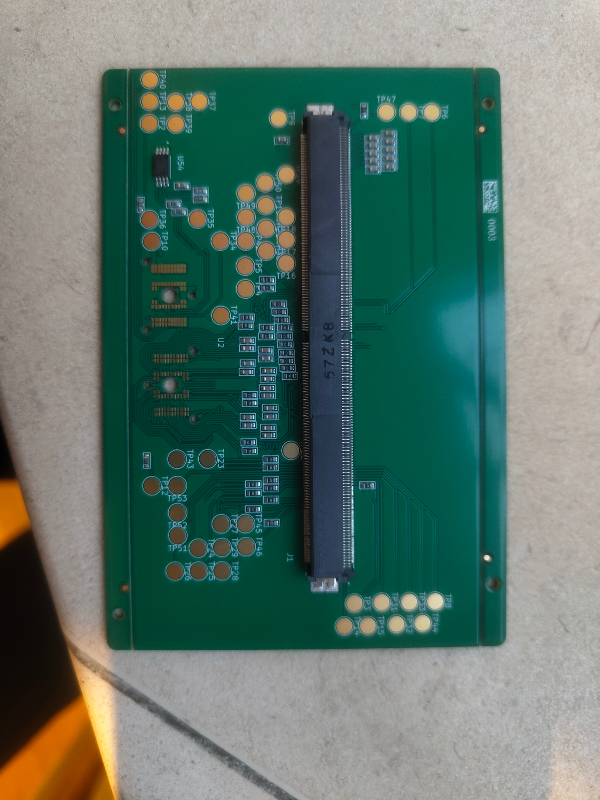
Ordered and in production
6 Likes
Such a good read. I have been thinking about getting a 30xx series MXM for an old Alienware 17 R1 to Tinker with since I’ve done a 980m upgrade before and got custom heatsinks and what have you. It would be fun to mess with on this platform too. It’ll keep my away from precision 7720 or the P71s of yesteryears
I know they’re unrelated but there’s a eBay seller that goes by cicichen, they make custom heatsinks for some of the cult followed laptops and a lot of Alienware stuff. I don’t know much about design but they could potentially be a good asset in this regard.
1 Like
It’s arriving today, but irony of all ironies my FW has decided to take an unresponsive nap. It’s not showing any power LEDs or fan noise and I’ve tried multiple chargers. Will update once I can get it up and working again and also once I try the new board.
2 Likes

And we’re back! Trickle charging with a slow usb charger did the trick I think. Fingers crossed.
4 Likes
EEPROM Flashed and everything’s booting on with the adapter plugged in. An interesting issue occurs though when I put in the MXM card - the 3.3v line and ground is shorted. The strange thing is that when I test 3.3v and ground on the MXM card I get nothing, and when i test 3.3v and ground on the adapter board I also get nothing. It’s only when they’re put together that the short occurs. Any ideas?
4 Likes
Shorts when connected.
Say some of the pins on the MXM are linked. I.e. 2 pins expected to be ground.
Say the connector has a short between say 3V and one of those 2 pins.
The short does not make its final link until the two are connected.
A short may also happen if there is a potential short within the main board, but it only connects once some strain is put on the mainboard. I.e. the MXM attached.
Things like this can be caught by making a test board in place of the MXM, that just breaks out the pins and test that for shorts, and levels etc.
1 Like
I believe it can happen if some pins are connected on the board, that are should be separate from adapter’s PoV. Something like this:

Also could be a misalignment due to imcompatible or loose connectors.
As well as misalignment of connector pins that has already been mentioned I would look at your PCB layout very carefully and make sure all the 3v3 pins on the connector ARE connected to 3v3, and all the ground pins ARE connected to ground. It can be very easy to get them crossed over and not notice - or on the schematic connect 3v3 or ground to the wrong connector pin, and the layout then slavishly follows the mistake.
Yep, I’m more and more leaning towards an issue with the card. Pretty sure it’s not the board as all the solder joints look perfect. I’ve checked both the 3.3v and GND pins and from what I can see at least initially they’re in the right place. I’m going to go over the card though and see what links I can find.
1 Like
Another thing to try to narrow down the fault.
See if you can fit some insulating tape over say, half the pins, and plug it it. Maybe Kapton tape.
This might be a way to narrow down which pins are shorting.
It could also be something simple, like the pins are mirrored. I.e. The pins on the bottom of the connector are supposed to actually be connected to the pins on the top of the card.
An easy problem to miss.
2 Likes
I’ve found the short I think. Looks like a third dead MXM GPU. BL_EN was shorted straight to 3.3 which definitely isn’t right. Another card coming soon.
4 Likes
Okay I’m out of ideas. I’ve tested every pin against 3.3v on the new card, and nothing is shorting. I’ve tested the adapter without anything in it, and nothing is shorting. Then they both go together and suddenly 3.3v and ground are connected together. There’s presumably something really obvious here but I just can’t find where.
I’m feeling out of options but I don’t want to give up. Does anyone have any interest, (with experience ideally), in being sent the dev board and an MXM card to test with?
Have you tried, as it was suggested before, masking parts of the connector with capton tape to see if any specific place is causing the issue?
Given both boards alone seem to work, the issue is probably in the connector itself or the way boards mate. Misalignment or accidentally mirrored layout? Are you sure you didn’t confuse front/back layers of the connector?
I can imagine a situation like this:

Due to incorrect heat profile, the adapter’s connector could experience slightly different thermal expansion, thus making extra connections that shouldn’t be there.
Couldn’t the issue also be that the 3.3V and GND pins are connected on the board. Maybe the pins are marked wrong on the symbol/footprint and it caused a 3.3V pin to be connected to GND (or the opposite) when it shouldn’t be? Dunno what else it could be