Hmm lots of ideas here. I’m in Denmark for the next few days so I’m not going to be able to do anything immediately, but when I get back, (and have access to a laser cutter), I think I’ll try the following:
I have two more V2 mxm board which I can test
The new MXM connector will still be fine for another go, hence
I’ll laser cut another stencil, possibly thinner to try and reduce solder paste spread, (please suggest materials!)
Then repaste and re assemble another board, again with fresh components bar the mxm connector
Rigorously check for shorts - though with 314 pins this could take a while
Try testing it again, looking at current draw.
I don’t have either a thermal camera or a power supply, so just doing things simply may be the only way forward.
You could use the same material and just cut smaller holes too.
Or pre-tin the pads for the connector and then hot air solder the connector (with the hot air heating the board from the bottom to not melt the connector).
You may want to add a lab power supply to your christmas list then XD (and maybe also a thermal camera, the things are not that expensive anymore)
Both sound great . The first stencil was manufactured by JLCPCB though out of metal, which I won’t be able to cut on the laser cutter I have access to.
Might try pretinning the pads though. I have attempted this previously but I’m suspicious it was what led to the first connector becoming warped, (they’re quite long and difficult to heat evenly on a large PCB, even from the bottom, but maybe just higher temperature for less time will solve it.)
The biggest issues I’ve had with pretinning is getting inconsistent amounts of solder across pads, leading to troubles with a component sitting flush. If you DO want to go that route AND you have a ‘knife edge’ solder iron tip, that might be helpful. If the drawing I’m looking at is accurate, there’s about 5mm between the two rows of pins for the MXM connector - the solder tip I’ve got on-hand is ~7mm wide. That might give just enough tip width to gently drag it from one end of the pins to the other while keeping the tip in contact with each pair of parallel pins, flowing solder as you go and creating a somewhat consistent amount of solder across all pins.
That’s obviously not a perfect method, but for prototyping it can be good enough.
With enough flux surface tension should produce a relatively predictable amount of solder per pad and the sitting flush thing should be resolved by doing the whole connector at once from the bottom. If you do it a couple pins at a time you’ll definitely have massive issues getting it to sit flush, especially with wide connectors. If your only option is to hand solder one pin at a time using an iron I would very much recommend against pre-tinning (except maybe the first and last pad or the outer ground pads if there are any to tack it into place)
Hallo again everyone. I’m back from Denmark and have some fixes as well. I’ve fixed the previously shorting board, (it was one of the fan headers), and have reflowed the mxm connector from underneath, which really seemed to help. Literally just about to plug it in for the first time. Thanks for all of your patience by the way; I’m excited to be back.
Hmm. I’m getting the feeling that this might be the gpu itself. It’s definitely getting 20v, so it’s surprising that it’s not even getting warm to the touch. I’m going to order a new cheap one now - I’ve just installed Ubuntu though so windows drivers won’t be as much of an issue any more. I’ll update again once I’ve bought something.
GPU should get here tomorrow, (ignore the one above), but I’ve been watching the new FW16 review on LTT short circuit, and they mention that you need a bios update for the gpu to work. Is this potentially what has prevented the gpu from showing up? thoughts?
My speculation would be that the new BIOS is needed for the new module to be supported by EC. I.e. the new (Nvidia) GPU would have different eeprom code which current bios doesn’t know about, and the new module supports chargibg through the back port, which EC most likely need to support as well.
So my thinking is that if you use the eeprom code which identifies as 7700S module, you shouldn’t have any problems.
Have you been in contact with Framework?
With the amount of work you’ve done (plus being at the point where not knowing could impede you) I would hope Framework could let you know if you’re running into a wall caused by the EC.
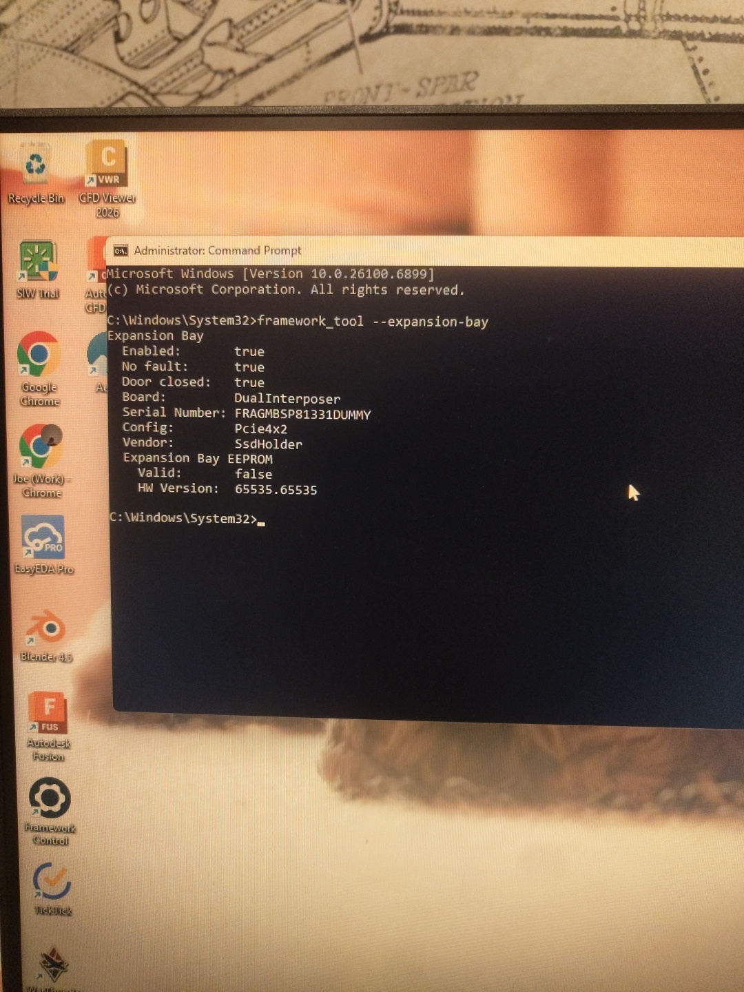
Fixed the EEPROM, card’s getting warm, but still nothing listed under Display Adapters . There’s something weird with the 3.3v line though that I’m going to try to fix…
It’s 2am here but I’ve got one last plan. This board still isn’t working. I’ve got no idea why. It’s passed all the continuity checks, the EEPROM is set correctly, but something is still going wrong. My intention therefore is to build the dumbest possible version of this board using one of the two remaining PCBs - just one TX pair, one RX pair, power, REFCLK, and PERST. No display port, no SDA/SCL, literally just the bare bones, and see if this goes anywhere at all. I’m going to actually mask off all the other connections to prevent any possibility of unintentional shorting.