How much power can the FW16 really supply to their USB4 ports

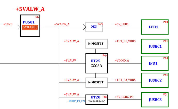
I have been looking at the FW16 AMD 7840HS public schematics while trying to work out what power can be supplied to the USB4 ports.

The SY8370C on the left can potentially output 11A.
This is then used to supply USB1 (higher current), USB2 (higher current), USB3(current limited). I assume those match up with Slot port 1, 2 and 3.

The USB3 uses the SY686B3ABC chip that is a current limiting chip, so has short circuit protection.

The USB1 has a N-MOSFET. Now a N-MOSFET has no current limit, so as the SY8370C can output 11A, one could potentially pass 11A through that N-MOSFET.
It does not say what component that N-MOSFET is, but I suspect it cannot handle 11A.
If there is a short on the USB-C port, there is no short-circuit protection on the N-MOSFET, so the N-MOSFET would probably melt. There have actually been reports of this N-MOSFET failing, so what can be done to protect the N-MOSFETs ? Answer: Nothing really.
The current restriction on the USB ports is that only one can supply 3A, the rest supply 1.5A. This works in a first one wins type approach.
So, electrically, can the FW16 supply more than that?
So, 3A is therefore capable for USB1, and also 3A is therefore capable for USB2, but it is currently software limited to only have one at a time.
There is also a USB4, 5 and 6 that have their own 11A supply.
So, it would appear that it would be safe to have slot 1 USB (the USB4 port on the left) supply 3A at the same time as slot 4 USB. (the USB4 port on the right).

Conclusions:

  1. Slot1, Slot2, Slot4, Slot5 do not have short circuit / over current protection so can melt the N-MOSFET. The upstream SY8370C does have short circuit / over current protection, so will not melt and prevent damage to other components. So, if the N-MOSFET does melt, it should be replaceable without too many other components also failing at the same time.
  2. It is a mystery why FW EC Firmware limits the USB ports to only have one slot win the 3A supply. It should at least be one slot on the left and one slot on the right win. It could potentially let 4 slots have 3A. Possible reason I can come up with, is that the publish FW16 7840HS schematic is wrong, and actually has problems with more than one slot being 3A.

Note: The FW13 AMD 7840U has very similar EC firmware as the FW16 AMD 7840HS, and the FW13 also has many more things drawing power of that supply rail. So maybe the limit of only one port at 3A is sensible for the FW13, but not particularly justified for the FW16. Maybe FW just did not bother changing the EC firmware for the FW16, and just reused the FW13 code.
Note: The FW Desktop uses the CYPD6228 chip that does USB4, and 3A output (with current limiting), so once FW fixed their EC firmware, the FW Desktop should be able to output 3A to both rear USB4 ports. FW cannot reuse code from the FW16 or FW13 to do that. It is a new chip, not used on other FW models.

What do other people think?
Is my analysis correct?
1 Like

Another observation.
Any attachments that might short circuit the slots 1,2,4,5 should be avoided on the FW16 7840HS.

  1. For example, Magnetic Charging Cables should be avoided, unless one wishes to melt the N-MOSFET.
  2. Any other USB devices that might short or over draw current.
  3. Anyone tinkering with USB-C breakout cables must take particular care not to short the VBUS to GND.
  4. Anyone attaching USB-C devices that they have made / built themselves must take particular care not to short the VBUS to GND.

Another observation:
In the USB specifications document, “11.4.1.1.1 Over-Current Protection”.
It states that it MUST have overcurrent protection for safety.
So, is the FW16 not compliant to the USB specification? Is it even fair to call them USB ports?

1 Like

As someone currently experience PD issues with my USB ports, this is interesting. Likely unrelated, but interesting.

I don’t want to derail this thread, but I’m curious. What issues are you having?

1 Like

I’ve been having an inconsistent issue where it just wont’ charge properly at 180W, instead it’ll throttle the processor to less than the battery’s capable power draw and only pull about 120W from the charger. Sometimes it won’t charge at all.

I think I might’ve figured out tonight what the issue is though: I think my cable went bad.

1 Like

Observation:

  1. Some NVME enclosures, when plugged in for a long time, randomly disconnect.
    Why is that. From the notes above, this cannot be due to over-current limiting by the FW, because it does not appear to have any over-current protection on the USB4 ports.
    So, the assumption about the over-current protection causing the NVME enclosure disconnects has therefore been wrong all along.
    So, what else could it be?
    a) noise, RF interference maybe? We have reports if people bypass the usb-c slot card, and plug directly into the usb-c socket on the mainboard, connections are more successful/reliable. So, definitely a possibility.
    b) USB protocol bugs. We already know the FW16 usb chips can reset with a simple “sudo lsusb -v”, so there are certainly bugs there.
    c) something else?
1 Like

I think the only way to test it is to use an electronic load(or use a resistor less than 1.6 ohm) to attempt to draw >3A and see whether the output is cut

There is an awful lot missing from the diagram in your first post.

To say that the FET is the only current limiting thing on a port will not be correct, there will be some form of low value current sense resistor in the picture somewhere, and the resulting voltage generated across that resistor will go to an IC which controls the gate of the FET, and will enforce the current limit. The same IC will be controlled from the processor or EC to turn the port off for what Windows euphemistically terms ‘power saving’ and will also generate the signal to the CPU to tell it when some new device has been plugged into the port.

There will be similar items on all the other ports somewhere, even if not specifically called out on that block diagram, to provide all the same facilities for the other ports.

1 Like

@Alan_Pearce
I think you might be right.
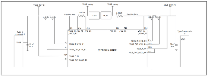
The FW diagram also has a CCG8D chip.

Extract from the CCG8D datasheet.

In that, one can see the current sense inputs (across 0.005 Ohm resistor) and NFET control output.

1 Like