Hey, just a quick thought that I mentioned to overclock as well, perhaps you can double check whether all the switches on the board are in the correct position.
I doubt it can be anything but an issue with the signal integrity in this case. The next batch of boards I ordered have some improvements to the signal routing, which should hopefully help. I’ll be sending one of the boards over to @Overheat for verification as it might help there.
It seems like in some scenarios a redriver or retimer might be required. I’ll see how it goes with the next revision of the board and if it still doesn’t work, I’ll see if I’ll proceed with a big batch or if it’ll be a smaller batch for people who are willing to risk it.
1 Like
I am not opposed to the idea of adding a redriver or retimer to make the signal integrity better. I was already planning to play around with the idea for a future revision of the board, but I do want to get a batch out to people who want to have it now as adding a retimer would take me months to figure out since its a bit more complicated component.
This can also highly depend on the GPU/CPU combo as the strength of the signals they send each other changes. So that might be why it’s getting at least something using the AMD GPU but basically nothing with the Nvidia.
It seems, that I indeed at some point swapped the direction of the modes in my mind.. I corrected it, but unfortunately, it didn’t really help. I still had poor performance in Windows, even though GPU-Z showed that the GPU was connected at 4.0x8. Interestingly, I once had full CPU clock speed and corresponding performance in Fedora with the eGPU connected (at least I think so, I’m starting to have doubts). After restarting again and switching to Windows, I couldn’t reproduce it again ![]()
I don’t know if it was a coincidence and it was able to establish signal integrity once, or if I simply have a bug somewhere in my configuration and it should actually work on the hardware side.
It seems to be really finicky using your setup. I never had any performance or connection issues in the last 4 months that I’ve been using the different revisions of the board (except issues with v4 BIOS) so it is a shame that there are configurations that have issues.
A lot of reading I have done about oculink says one of the biggest factors to cause issues is the cable. They can be super picky and sometimes you might just get one that doesn’t work. For example, with the DEG1 you had to use their cable. If you tried to use a different one, more often than not, it did not work. Secondly is the length. They are not optimized to operate at a distance and signal integrity diminishes. Max length I’d go is 2ft, but the shorter the better.
@Filip
Do you have a URL for your latest board design. I might have some feedback comments.
Looking at one of your 8i design you have length correction (Serpentine). Maybe consider placing the serpentine closer to where the length change happens. So that the N and P signals are kept in sync along as much of the pair as possible.
See if you can reduce the amount of 180 Vias. I.e. where the via exit is not in the same direction as the via entry.
The FAN 12V and PWM lines, a source of some noise is probably too close to the TX6+/TX6- and TX4+/TX4- high frequency lines.
I would suggest routing the FAN traces across the middle of the board across to the right hand fan, with multiple vias, rather than very close to the high frequency traces, with no ground between the 12V/PWM/Sense and high frequency signal trace.
I suspect that is maybe the most likely cause of your problem keeping the 8x lanes connected, and it falling back to 4x lanes.
Also, try not to have high frequency traces too close to the edge of the board or too close to holes in the board. Try to have some ground between the trace and the edge of the board, or edge of the hole.
I’m in NRW, would it be possible to pick it up before you leave to Tokyo?
Finally had a bit of time today to sit down and measure out my eGPU board. Dimensions below are in millimeters.
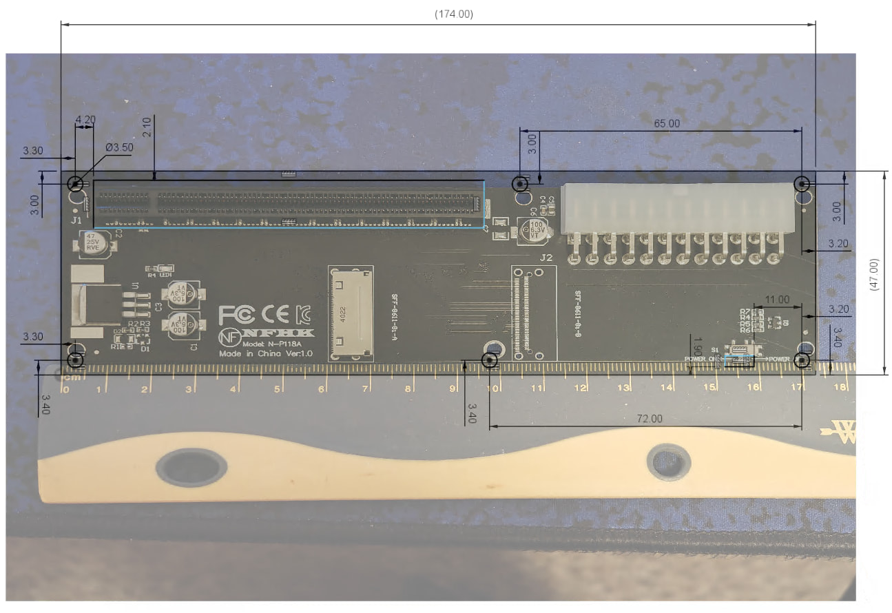
I’d ask that anyone with decent calipers and/or ruler please contribute to the form here: NFHK Oculink 8i To PCI Express 4.0 x16 Adapter Variants
For those who don’t have the means or trust their measurements, I’d still be happy to take in photos of their boards alongside rulers (similar to the one pictured above) using the form. I’ll share a link to the results once they start to come in, as well, in the spirit of keeping things open. ![]()
Update a few hours later - here’s the spreadsheet for folks to view as it gets populated; NFHK Oculink 8i To PCI Express 4.0 x16 Adapter Variants (Responses) - Google Sheets
Still aiming to have some time in March to draft up a mount for the eGPU board and do some test fits.
2 Likes
I’ll have to pull mine off there to snap a photo. I’ve not got fancy tools, but I’m sure I could scrounge a ruler to get a photo. According to the image they provided on the website, this should be what mine is:
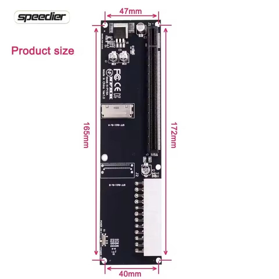
But as I mentioned previously, I bought the same one Filip did and it did not match up with his provided 3D print that he uses for his board. I know printers can have some slight misprints on occasion, but locations to align screws did not match up so I’m not sure what’s going on there. Unless manufacturer doesn’t have consistency for fastening? Beats me..
1 Like
Sure looks like the one in my hands - I got mine from Amazon just because I wanted it quickly so I could start modeling sooner than AliExpress would get something here (and also, the uncertainty around imports/US tariffs/etc). Entirely possible there’s a Ver 1.1 that you have that rearranges things, too. Curious to see what you find when you have the time to peek at your board.
Funny thing is that their measurements are different from my board, though. They might be rough, or I might have the same issue you’re experiencing. I’ll peek at Filip’s model today and see what his positions are relative to what I measured.
Just checked Filip’s model - that model absolutely has hole placement that deviates from my measurements by ~3mm along the length of the board.
@OVER_CL0CK , did I interpret correctly that you have a 3D printer? I can whip up a really basic alignment “blank” for you to print, if so, to test whenever you pop your eGPU out for a photo.
I do not personally, reached out to a friend to have them print for me only to find out it didn’t work unfortunately. Also, Filip designed his for an SFX psu where as I use an ATX for my card. So the support arm that holds the gpu up via the back of the psu didn’t line up either. That was entirely my fault for not paying attention. I would likely need a whole new revision.
I intend to make an enclosure/adapter set that works for multiple PSU types - I’d like to have either different plates or adapter plates included so you could use SFF or ATX or maybe even other PSU variants (if there’s interest in the community), so we’ll get there. ![]()
Let me know if you’d still be interested in the test-fit “blank” I mentioned, though. (That goes for anyone else following the thread, too.) Happy to model it up for folks to do comparisons against their NFHK eGPU boards.
1 Like
That project sounds awesome. Honestly I don’t expect anything fancy, and even don’t mind the open concept for egpu. Mainly I just need something solid to hold everything together ![]() . The frankenstein I have right now is not a long term solution. I’m at work right now and will need to get home to pull the board and get the image for you.
. The frankenstein I have right now is not a long term solution. I’m at work right now and will need to get home to pull the board and get the image for you.
1 Like
Thanks for the feedback, I made sure to implement some of it in the design. I did just push the latest changes to the repo so the KiCad project can be viewed.
@Filip
I see you have done a lot of work with changing the PCB traces / routing.
It is looking pretty good now.
The only thing I can see is RX2 and RX5 traces go very close to the hole near the interposer end of the trace.
It does look somewhat difficult to improve, so I don’t know what to do there.
There is a method whereby one can place a via at the interposer connector pads, but although possible, probably results in a more expensive PCB manufacture, so I doubt that is an option here.
It is a shame that FW have not published example PCBs with the routing/traces so one can see an example of good for the interposer end of the traces. For example, including the dual SSD PCB traces / routing in the dual SSD expansion board git repo would have been really helpful.
I do know that the most complicated part of any design is the PCB routing, so I can understand why they might not wish to include it. We have designs at work that use 28 layer PCBs, and those take a crazy amount of time to get right.
@Andrew_Shaffer the provided measurements on the image I sent you seem off based on what I am getting on my tape measure. Couldn’t seem to find a ruler surprisingly. Granted, not perfect (and certainly can’t take a photo with my tape in hand) but next best thing was showing 41.275mm from centerpoints of mounting holes for both top and bottom and 182.5625mm on both long sides from center to center of mounting points. I’ll see if I can find a ruler and cross check…
Edit: found a ruler. I was dang close with my tape. 41mm top and bottom and 182mm for the sides.
2nd Edit: total length across top and bottom is 47mm and sides are 188mm
3rd Edit: I don’t know why I didn’t look at this earlier. My board indeed looks like yours, but says Version 2.0
1 Like
So we do have a Version 2 to account for! That’s going to be important. Should be able to accommodate both, as long as I get some of those key distances from the V2 board.
Here’s a refined version of the V1.0 eGPU based on my measurements and a test print today;

Updating my spreadsheet here; NFHK Oculink 8i To PCI Express 4.0 x16 Adapter Variants (Responses) - Google Sheets
Sounds like you’ve got the dimensions for the corner mounting holes; any chance you could determine distance from the holes at the power input end of the board to the middle mounting holes? If so, I can get a mockup together for it. I feel like the added mounting point at the end of the PCI slot in particular would be important to prevent too much flexing when attaching/removing a GPU in an enclosure.
Edit: Just dropped the test jig for v1.0 here if anyone with a 3D Printer wants to give it a run:
1 Like