
We’ve developed an RTC Battery Substitute module that can sit in place of the coin cell battery to keep the RTC circuit powered. Note that this does require soldering a single wire on the top side of the Mainboard. We are currently preparing the process for requesting this module, but have published the guide for it in the meantime.
If you have an 11th Gen system or Mainboard, you can now reach out to support to request a free RTC Battery Substitute module. To make the request process go smoothly, enter the email address that you ordered the 11th Gen product on and/or include photos of the system and Mainboard serial numbers.
Note that there are no constraints making this request other than being an 11th Gen system or Mainboard owner (whether or not you are in warranty). We ask that you really make sure you are comfortable with performing soldering on expensive electronics items before performing the installation, as we won’t be able to provide advice or support around soldering or provide fixes for failed soldering attempts. We also ask that you only make the request if you’ve faced needing to perform a Mainboard reset, as we want to avoid waste.
Archived: an earlier, more complicated rework
@Kieran_Levin has prepared the instructions below for folks who are interested in performing the rework mentioned in this earlier post.
Rework Instructions for 11th Gen Mainboards to enable RTC Battery charging from the main battery
Before you consider this rework, please note that it requires advanced soldering skills, requiring cutting traces on the Mainboard and soldering to small pads and traces. Damaging the Mainboard during the rework process would not be covered under warranty, and we’re unable to provide repair services to attempt to repair failed reworks.
This rework modifies the RTC battery circuit on 11th Gen Mainboards to follow a behavior closer to 12th Gen Mainboards. On 11th Gen, the default behavior is for the RTC battery to recharge only when AC is attached, while on 12th Gen, the RTC circuit and RTC battery are charged off of the main battery. With the rework, this means that when the laptop is left disconnected from power over long periods of time, the RTC battery will remain charged. This will not measurably impact main battery life.
This rework also allows the 11th Gen Mainboard to be used without an RTC battery in many cases. However, if the laptop’s main battery is fully discharged and left for extended periods or the laptop is placed in cold temperatures below 0°C, the main battery will disconnect due to protection conditions being triggered, resulting in the RTC circuit also powering down. The impact of that is the system clock resetting, which your operating system will correct after syncing with a network time server. If the main battery is fully discharged, the system will of course also need to be plugged into power to recharge and power up again.
Items needed for rework
- Precision hobby knife (e.g. Xacto knife)
- Soldering iron with a fine tip
- 499k or 500k ohm resistor 0402 size or similar
- 150k ohm resistor 0402 size or similar
- Schottky Diode rated for 100mA 30V. This will be jumper wired across the top side of the Mainboard, so size is not too critical.
- Fine single strand jumper wire. For example, 30AWG or smaller wire wrap wire.
- Multimeter to check that the cutting and soldering was successful
- (Recommended) Microscope or magnifying glass
Rework Overview
This rework will enable a 3.3V LDO on the PU301 regulator that we will connect to the RTC charging circuit so that the RTC battery will always be charged/powered even when the system is fully off and shutdown using the main battery. This modifies the RTC charging path, so we will also connect one additional source to the RTC charging path through a diode to allow the system to power up even if the main battery is dead and the RTC battery is also dead.
Step 1 - Remove the Mainboard and RTC battery
Remove the Mainboard from your laptop, and remove the RTC battery. You can follow steps 1 through 6 in the Mainboard Reset Guide for this. You can follow the steps through step 16 in the Mainboard Guide to remove the Mainboard.
Step 2 (the most difficult step) - Cut the trace
Locate PU301 on the bottom side of the Mainboard near the bottom left corner.
Cut the trace to the upper right pin, between the Via and the pin. Be careful not to cut into the via area, as this will prevent the 5V regulator from turning on.
Cut here:
Step 3 - Check that the trace is cut
Check the LDO EN signal is properly cut by checking that the resistance is open between the EN pin on PU301 and PU502 with a multimeter. Use a DMM (digital multimeter) to probe the following two pins and make sure they are not close to 0 ohms.

Step 4 - Build a resistor divider
Using the 150k and 499k resistors and the thin wire, build a resistor divider between the system rail (VSYS) and GND and connect it to the EN pin of PU301. This will power on the internal LDO of PU301 whenever the main battery is connected or a charger is attached.


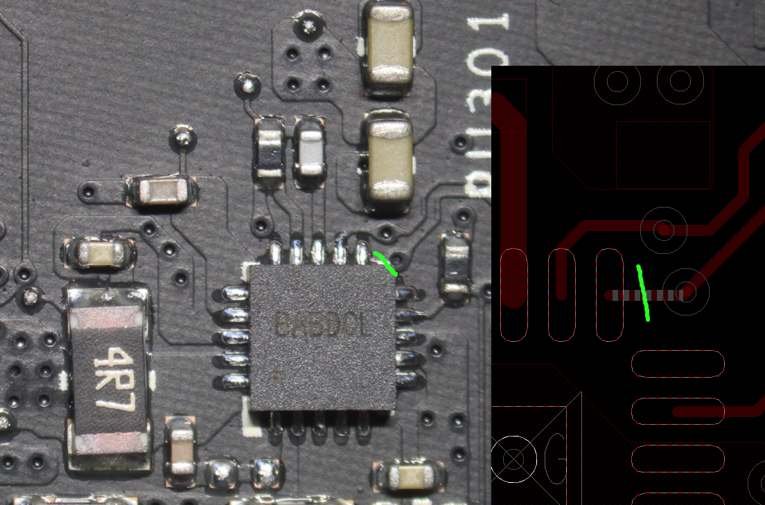
Step 4 - Cut the trace
On the top side of the Mainboard, just below the SSD fastener, there is an unpopulated resistor footprint with a short trace. Cut the trace in this pad. Measure the resistance between the two sides of the pads with your multimeter to confirm the cut has broken continuity.
Step 5 - Connect the LDO output
Flip the Mainboard back over to look at the bottom side. Using a thin wire, connect the LDO output to the RTC charging net input. You may want to apply some kapton tape or other thin, non-conductive tape over the cable to prevent it from touching any part of the housing.


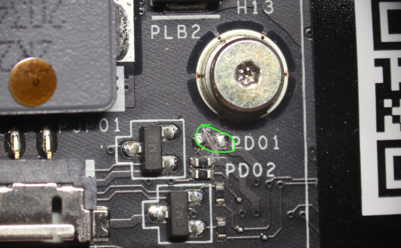
Step 6 - Connecting to the RTC Battery circuit
Flip the Mainboard back over to look at the top side. Connect a diode to the RTC battery diode package from the 3V_EC regulator. This ensures that the Mainboard will turn on when the battery is disconnected and the RTC battery is dead. The reason for this is the EC (Embedded Controller) power will come up before the power output from the PU301 regulator, so the RTC voltage also needs to come up at the same time, otherwise the EC will not power on.


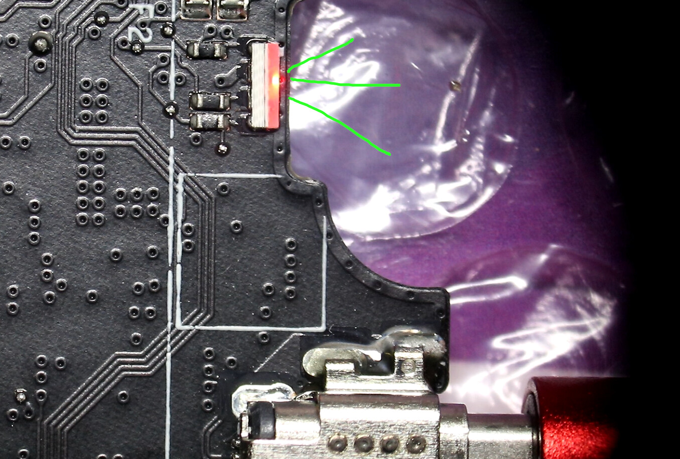
Step 7 - Initial Validation
Without installing the Mainboard into the system and with the RTC battery still removed, plug a USB-C power adapter in and check that the side LEDs flash. This means the EC has successfully initialized, and the RTC circuit can power on with the system.
If the side LEDs do not turn on, check for voltage in the RTC battery holder.
Step 8 - Install the Mainboard
Follow steps 17 through 28 to assemble the Mainboard into the system and plug in the battery. Ensure the system powers on without the RTC battery installed and with the main battery attached. Optionally, reinstall the RTC battery.
Step 9 - Complete assembly of the Laptop
Follow the rest of the Mainboard Guide to complete assembly of your laptop. Great work!
